Compact and efficiently cooled fan motor

a fan motor, efficient technology, applied in the direction of positive displacement liquid engines, piston pumps, liquid fuel engines, etc., can solve the problems of uneven cooling of components of the fan motor, unbalanced air flow, and the cooling structure of the fan motor itself, so as to reduce the size of the fan boss

Inactive Publication Date: 2006-05-04
DENSO CORP +1
View PDF0 Cites 35 Cited by
  • Summary
  • Abstract
  • Description
  • Claims
  • Application Information

AI Technical Summary

Benefits of technology

[0011] The above-mentioned problem being taken into consideration, the object of the present invention is to provide a fan motor in which the flow rate of the ventilation air within the fan motor is increased and the size of a fan boss is reduced.

Problems solved by technology

Conventionally, a fan motor used for cooling an engine, etc., of a vehicle is arranged in an engine compartment to which radiant heat from an engine is transferred and therefore, a cooling structure for the fan motor itself is a design problem to be solved.
However, in the above-mentioned prior art, as an air flow path in a motor case between a ventilation inlet for air flow-in and a ventilation outlet for air flow-out in the motor case is squeezed by the air gap, the air flow is formed in an unbalanced state (most of the air flows through one side) in the air flow path in the motor case.
That is, there is a problem that the components of the fan motor were unevenly cooled by the air flow.
In addition, the air flow resistance in the air gap is relatively large, and therefore, the flow rate of the ventilation air in the motor case is restricted which is a problem to be solved.
In other words, there are cases in which it was difficult to sufficiently cool the members to be cooled.
Moreover, in the above-mentioned prior art, as cooling blades are provided on the inner bottom surface of the fan boss in order to increase the ventilation air flow rate inside the motor, it is necessary to provide a space for accommodating the cooling blades on the inner bottom surface of the fan boss and, therefore, there was a problem that the size of the fan boss was increased.
Therefore, there was a problem that the air flow to the outside of the motor case was disturbed by the pressure produced by the fan-blade and the cooling efficiency of the inside of the motor was degraded.

Method used


Image

  • Compact and efficiently cooled fan motor
  • Compact and efficiently cooled fan motor
  • Compact and efficiently cooled fan motor

Examples


first embodiment

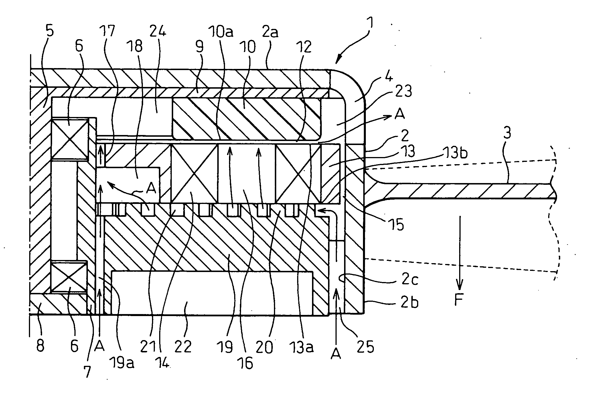
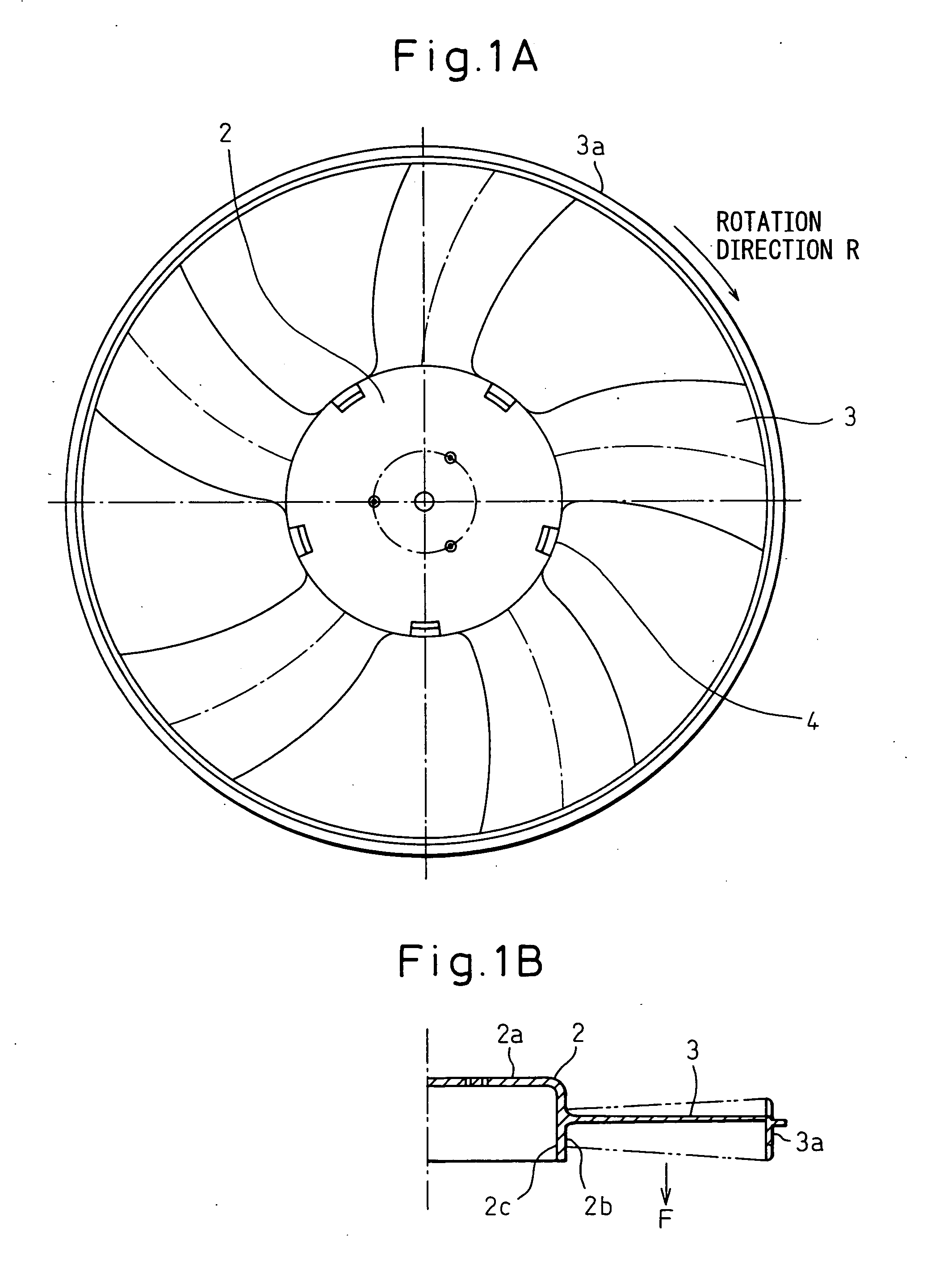
[0055] A first embodiment of the present invention is described below with reference to figures. FIG. 1A and FIG. 1B are a top plan view and a cross-sectional view of a fan boss 2 and a fan-blade 3 in a fan motor 1 according to the first embodiment. FIG. 2 is a sectional view of the inside of the fan boss 2 and FIG. 3 is a partially cut-off sectional perspective view of the fan boss 2 without the fan-blade 3. FIG. 4 is a perspective view of a rotary magnet 10.

[0056] In the first embodiment of the present invention, the fan boss 2 is formed in a cylindrical shape. A cylindrical member, that is, a portion having a cylindrical shape, accommodates the components of a motor and at the same time, the fan-blade 3 which produces an air flow F in an axial direction of the cylindrical member by the rotation of the fan boss are integrally formed on an outer side face 2b of the cylindrical member. In the present embodiment, the fan-blade 3 has five blades. The blade shape of the fan-blade 3 at...

second embodiment

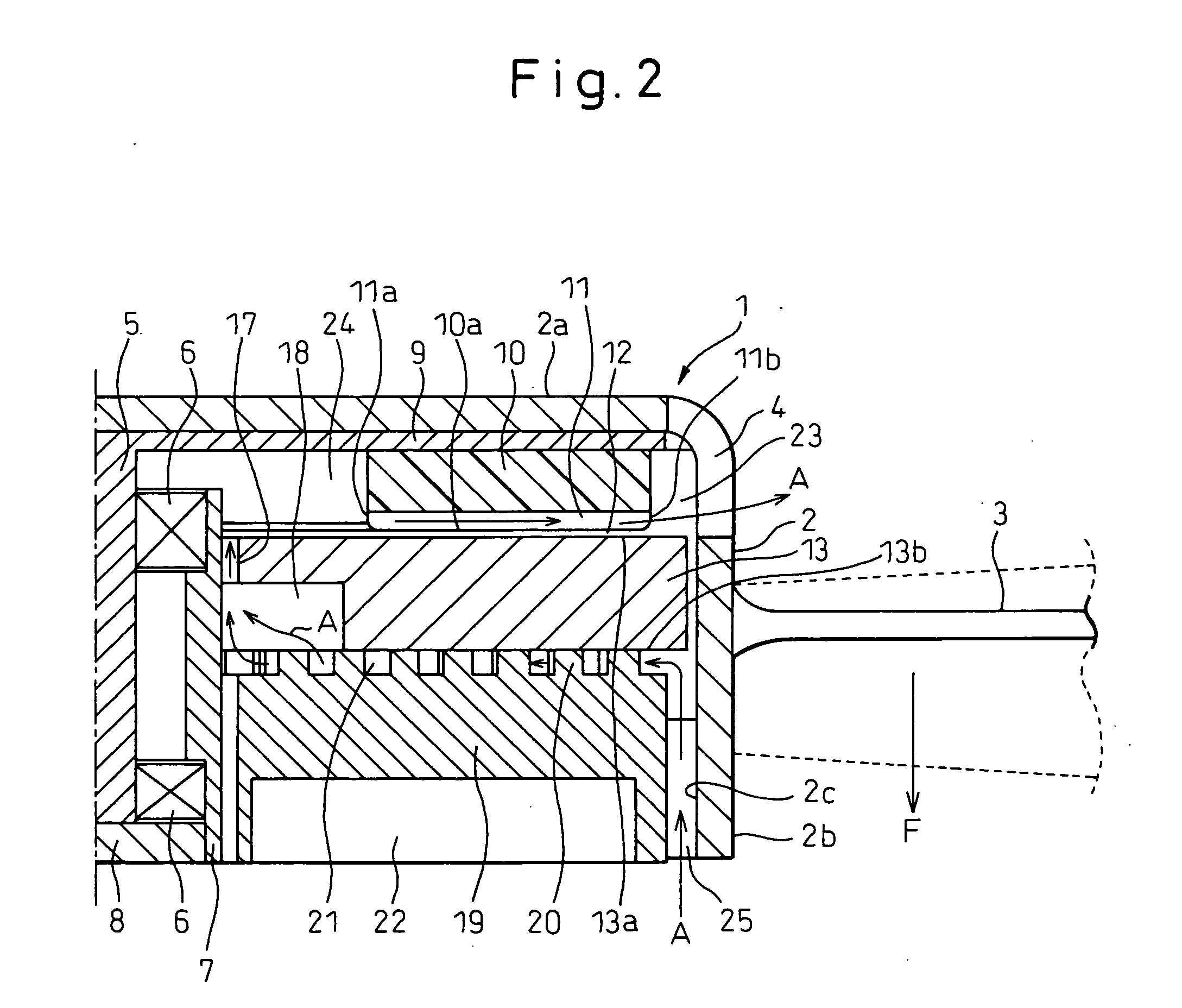
[0070] A second embodiment of the present invention is described below with reference to figures. FIG. 1A and FIG. 1B are a top plan view and a cross-sectional view of a fan boss 2 and a fan-blade 3 in a fan motor 1 according to the second present embodiment. FIG. 8 is a sectional view of the inside of the fan boss 2 and FIG. 9 is a partially cut-off sectional perspective view of the fan boss 2 without the fan-blade 3. FIG. 10 is a plan view of a stator 13.

[0071] In a first embodiment of the present invention, the fan boss 2 is formed in a cylindrical shape. A cylindrical member, that is, a portion having a cylindrical shape, accommodates the components of a motor and at the same time, the fan-blade 3 which produces an air flow F in an axial direction of the cylindrical member by the rotation of the fan boss is integrally formed on an outer side face 2b of the cylindrical member. In the present embodiment, the fan-blade 3 has five blades. The blade shape of the fan-blade 3 at the t...

third embodiment

[0094] A third embodiment of the present invention will be explained below with reference to the figures. FIG. 11A and FIG. 11B are a top plan view and a sectional view of a fan boss 2 and a fan-blade 3 in a fan motor 1 according to the present embodiment. FIG. 12 is an exploded view from the side direction of the fan boss 2.

[0095] In the present embodiment, the fan boss 2 has a cylindrical shape comprising a bottom surface 2a . A front portion of an electric motor 106 is received in the cylindrical member of the fan boss 2, and a shaft 5 that is an output shaft (rotating shaft) of the electric motor 106 and the bottom surface 2a of the fan boss 2 are fixed to each other so that each of the rotating axes coincide with each other.

[0096] An axial flow type fan-blade 3 for producing an air flow F in the rotating axis direction by the rotation of the fan boss 2 are integrally formed on the outer side surface 2b of the cylinderical member of the fan boss 2. In the present embodiment, t...


PUM


Abstract

A rotor magnet 10 and a stator opposing each other are accommodated in a cylindrical fan boss. Groove-like radial ventilation paths are formed on the rotor magnet and fan boss holes are formed in the axial positions corresponding to those of the outer circumferential side fan boss openings. The rotor magnet and the fan-blade driven to rotate by the motor produce an air flow F on the outside of the fan boss. An air flow in the radial ventilation paths flowing to the outer circumferential side is produced and increased by a centrifugal force and a negative pressure generated at the outer circumferential side. The increased air flow is positively discharged from the fan boss holes in the same position in the axial direction as the radial ventilation paths to the outside of the fan boss located at the negative pressure side of the fan-blade.

Description

BACKGROUND OF THE INVENTION [0001] 1. Field of the Invention [0002] The present invention relates to a fan motor. [0003] 2. Description of the Related Art [0004] Conventionally, a fan motor used for cooling an engine, etc., of a vehicle is arranged in an engine compartment to which radiant heat from an engine is transferred and therefore, a cooling structure for the fan motor itself is a design problem to be solved. For example, there is a prior art in which, when blades of a fan for moving air rotate, the air flows through the inside of a case of the fan motor to efficiently cool members in the fan motor by sucking and discharging the air from respective ventilation outlets (openings) provided on a front side and a rear side of the case of the fan motor (for example, refer to Patent document 1). [0005] That is, in the prior art, a cylindrical fan boss, which is arranged so as to cover the motor case, supports the blades of the fan and is rotated by a motor, is arranged to cover the...

Claims


Application Information

Patent Timeline
Patent Type & Authority Applications(United States)
IPC IPC(8): H02K9/00F04B35/04F04B17/00
CPCF04D25/0653F04D29/584F04D25/082F04D29/5806
Inventor IWASAKI, TAKUHIROODA, SHINICHIIZUMI, KAZUYUKI
Owner DENSO CORP
Why Eureka
Try Eureka