Method and system for battery protection

a battery protection and battery technology, applied in the field of battery protection methods and systems, can solve the problems of irreversible damage to batteries, excessive heat build-up, and excessive overdischarge conditions, and achieve the effect of shortening the life of the battery pack

Active Publication Date: 2006-05-04
MILWAUKEE ELECTRIC TOOL CORP
View PDF90 Cites 230 Cited by
  • Summary
  • Abstract
  • Description
  • Claims
  • Application Information

AI Technical Summary

Benefits of technology

[0007] Some battery chemistries (such as, for example, Lithium (“Li”), Lithium-ion (“Li-ion”) and other Li-based chemistries) require precise charging schemes and charging operations with controlled discharge. Insufficient charging schemes and uncontrolled discharging schemes may produce excessive heat build-up, excessive overcharged conditions and / or excessive overdischarged conditions. These conditions and build-ups can cause irreversible damage to the batteries and can severely impact the battery's capacity. Various factors, such as, for example, excessive heat, can cause one or more cells within the battery pack to become imbalanced, that is, to have a present state of charge that is substantially lower than the remaining cells in the pack. Imbalanced cells can severely impact the performance of the battery pack (e.g., run-time and / or voltage output) and can shorten the life of the battery pack.

Problems solved by technology

Insufficient charging schemes and uncontrolled discharging schemes may produce excessive heat build-up, excessive overcharged conditions and / or excessive overdischarged conditions.
These conditions and build-ups can cause irreversible damage to the batteries and can severely impact the battery's capacity.
Various factors, such as, for example, excessive heat, can cause one or more cells within the battery pack to become imbalanced, that is, to have a present state of charge that is substantially lower than the remaining cells in the pack.
Imbalanced cells can severely impact the performance of the battery pack (e.g., run-time and / or voltage output) and can shorten the life of the battery pack.

Method used


Image

  • Method and system for battery protection
  • Method and system for battery protection
  • Method and system for battery protection

Examples


Embodiment Construction

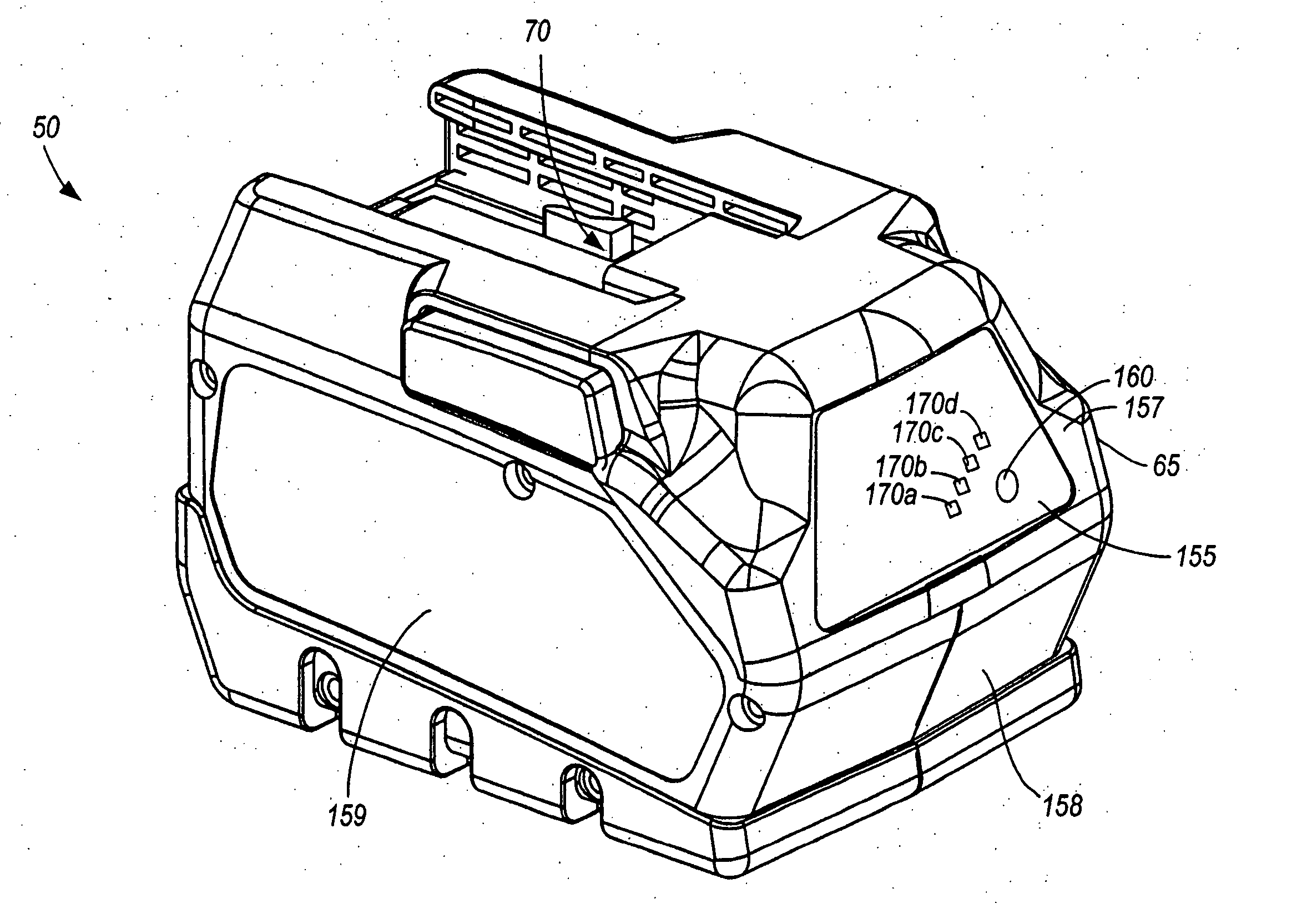
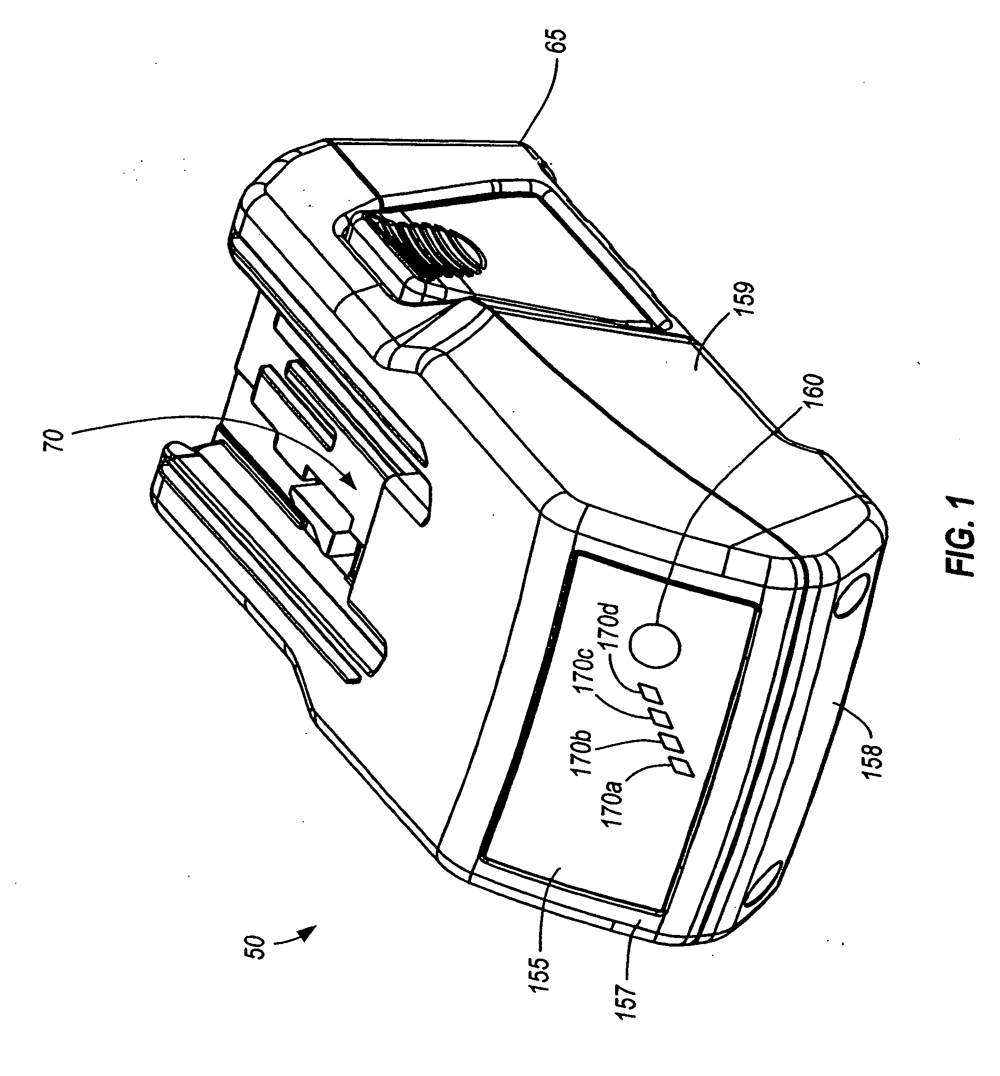
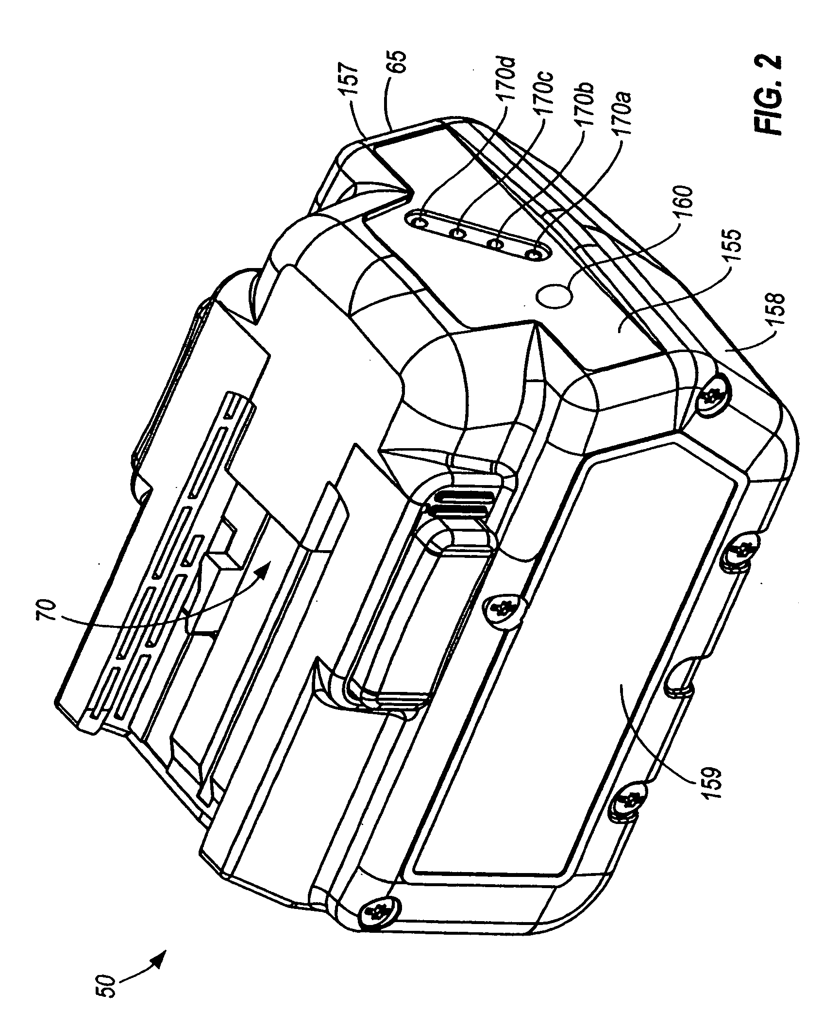
[0126] A battery pack or battery 50 is illustrated in FIGS. 1-3. The battery 50 can be configured for transferring power to and receiving power from one or more electrical devices, such as, for example, a power tool 55 (shown in FIGS. 4-5), a battery charger 60 (shown in FIG. 24) and the like. As shown in the constructions illustrated in FIGS. 4 and 5, the battery 50 can transfer power to various power tools, such as, for example, a circular saw 56, a driver drill 58, a reciprocating saw (not shown), a band saw (not shown), an impact wrench (not shown), a right-angle drill (not shown), a work light (not shown) and the like. In some constructions and in some aspects, the battery 50 can supply a high discharge current to electrical devices, such as, for example, a power tool 55, having high-current discharge rates. For example, the battery 50 can power a wide range of power tools 55 including a circular saw 56, a driver drill 58, and the like, as shown in FIGS. 4 and 5 and mentioned a...


PUM


Abstract

A method of conducting an operation including a battery. The battery includes a cell having a voltage. Power is transferable between the cell and the electrical device. A controller is operable to control a function of the battery pack. The controller is also operable with a voltage at least one of equal to and greater than an operating voltage threshold. The cell is operable to selectively supply voltage to the controller. The method includes the act of enabling the controller to operate when the voltage supplied by the cell is below the operating voltage threshold.

Description

RELATED APPLICATIONS [0001] The present patent application claims the benefits of prior filed co-pending U.S. provisional patent application Ser. No. 60 / 574,278, filed on May 24, 2004; Ser. No. 60 / 574,616, filed on May 25, 2004; Ser. No. 60 / 582,138, filed on Jun. 22, 2004; Ser. No. 60 / 582,728, filed on Jun. 24, 2004; Ser. No. 60 / 582,730, filed on Jun. 24, 2004; Ser. No. 60 / 612,352, filed on Sep. 22, 2004; Ser. No. 60 / 626,013, filed on Nov. 5, 2004; Ser. No. 60 / 626,230, filed on Nov. 9, 2004; and Ser. No. 60 / 643,396, filed on Jan. 12, 2005, the entire contents of all of which are hereby incorporated by reference. [0002] The present patent application also claims the benefit of prior filed co-pending U.S. patent application Ser. No. 10 / 720,027, filed on Nov. 20, 2003, which claims the benefit of prior filed co-pending U.S. provisional patent application Ser. No. 60 / 428,358, filed on Nov. 22, 2002; Ser. No. 60 / 428,450, filed on Nov. 22, 2002; Ser. No. 60 / 428,452, filed on Nov. 22, 2002...

Claims


Application Information

Patent Timeline
Patent Type & Authority Applications(United States)
IPC IPC(8): H02J7/00H01M50/204H01M50/227H01M50/247H01M50/296
CPCB25F5/00Y02E60/122H01M2/1016H01M2/1022H01M2/1055H01M4/505H01M10/0525H01M10/4207H01M10/425H01M10/441H01M10/46H01M10/482H01M2200/00H02J7/0011H02J7/0026H02J7/0031H02J7/0045H02J7/0063H02J7/041H02J7/042G01R31/3606G01R31/382H01M10/4257H01M2010/4271H01M2010/4278H01M2220/30H02J7/0071B25F5/008H02J7/0016H02J7/0014H02J7/0034Y02E60/10H01M50/213H02J7/04H02J7/00302H02J7/00309H02J7/00306H02J7/00308H01M50/204H01M50/227H01M50/296H01M50/247H02J7/00
Inventor JOHNSON, TODD W.ROSENBECKER, JAY J.MEYER, GARY D.ZEILER, JEFFREY M.GLASGOW, KEVIN L.ZICK, JONATHAN Z.BROZEK, JEFFREY M.SCHEUCHER, KARL F.
Owner MILWAUKEE ELECTRIC TOOL CORP
Why Eureka
Try Eureka