Planar microwave line with a directional change

a directional change, microwave technology, applied in the direction of waveguides, multiple-port networks, electrical apparatus, etc., can solve the problems of undesirable signal corruption, shifts in the electrical ground zero point, and electrical field field, and achieve the effect of reducing wave impedance and counterbalancing wave impedan

Active Publication Date: 2006-05-04
ATMEL CORP
View PDF4 Cites 3 Cited by
  • Summary
  • Abstract
  • Description
  • Claims
  • Application Information

AI Technical Summary

Benefits of technology

[0017] In addition to length uniformity, extensive constancy of the microwave line wave impedance, which depends on the gap of the microstrip conductor, is further achieved by the invention. Sections with a larger gap and thereby greater wave impedance and sections with a smaller gap and thereby lower wave impedance counterbalance in the ideal case.
[0018] Furthermore, a periodic modulation of the gap occurs as the result of a periodic folding of at least one inner edge, which has a certain wavelength.
[0019] An inner edge can be lengthened as desired by such periodic folding and thereby matched to the length of another outer edge of an adja

Problems solved by technology

It is also known that discontinuities in the signal path such as open ends, feed-throughs through the dielectric, wave resistance jumps, crossing of lines, or directional changes, for example, breaks in the path of lines, produce distortions in the electromagnetic fields, which corrupts transmitted signals.
With directional changes, as occur

Method used


Image

  • Planar microwave line with a directional change
  • Planar microwave line with a directional change
  • Planar microwave line with a directional change

Examples


Embodiment Construction

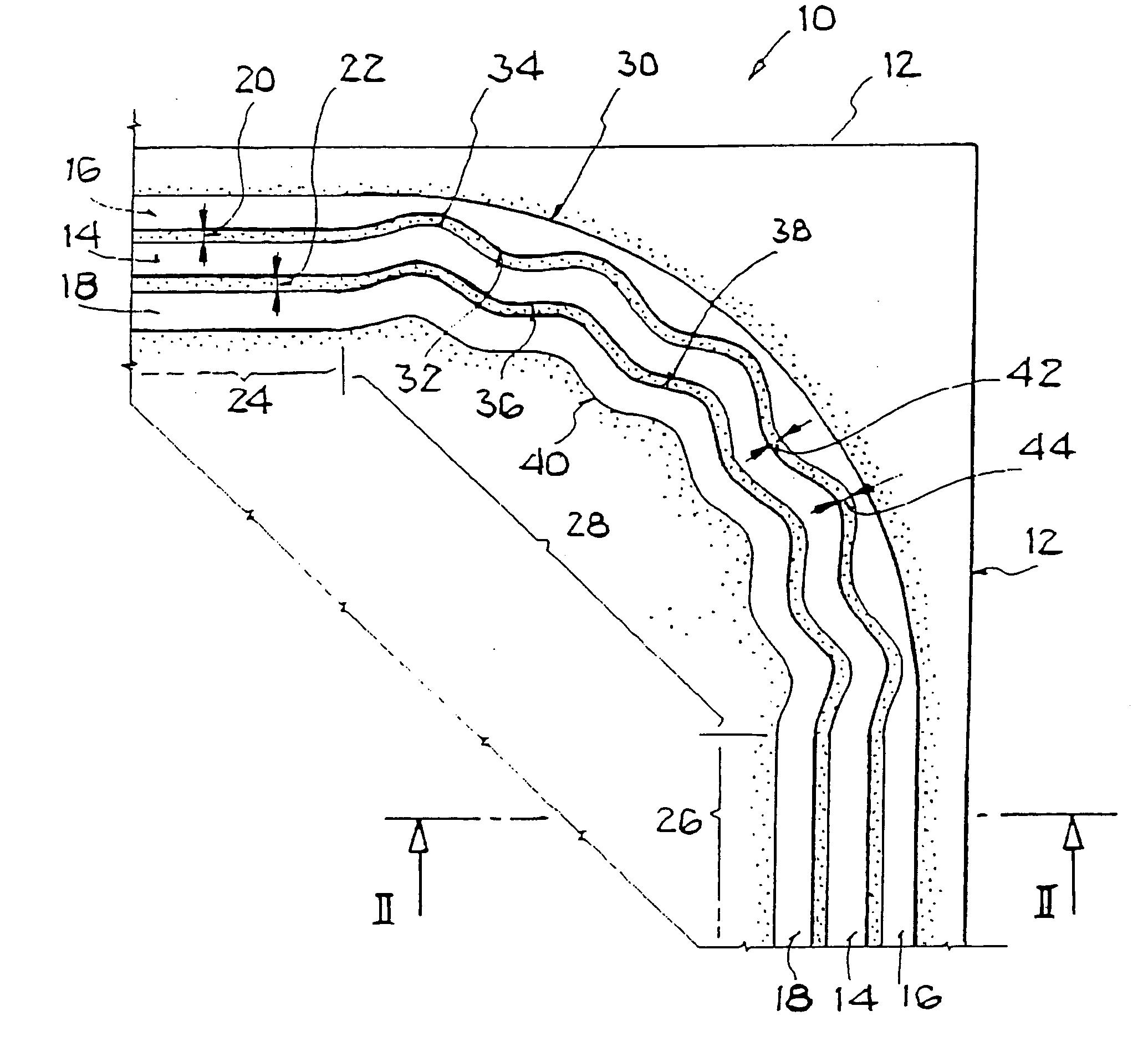
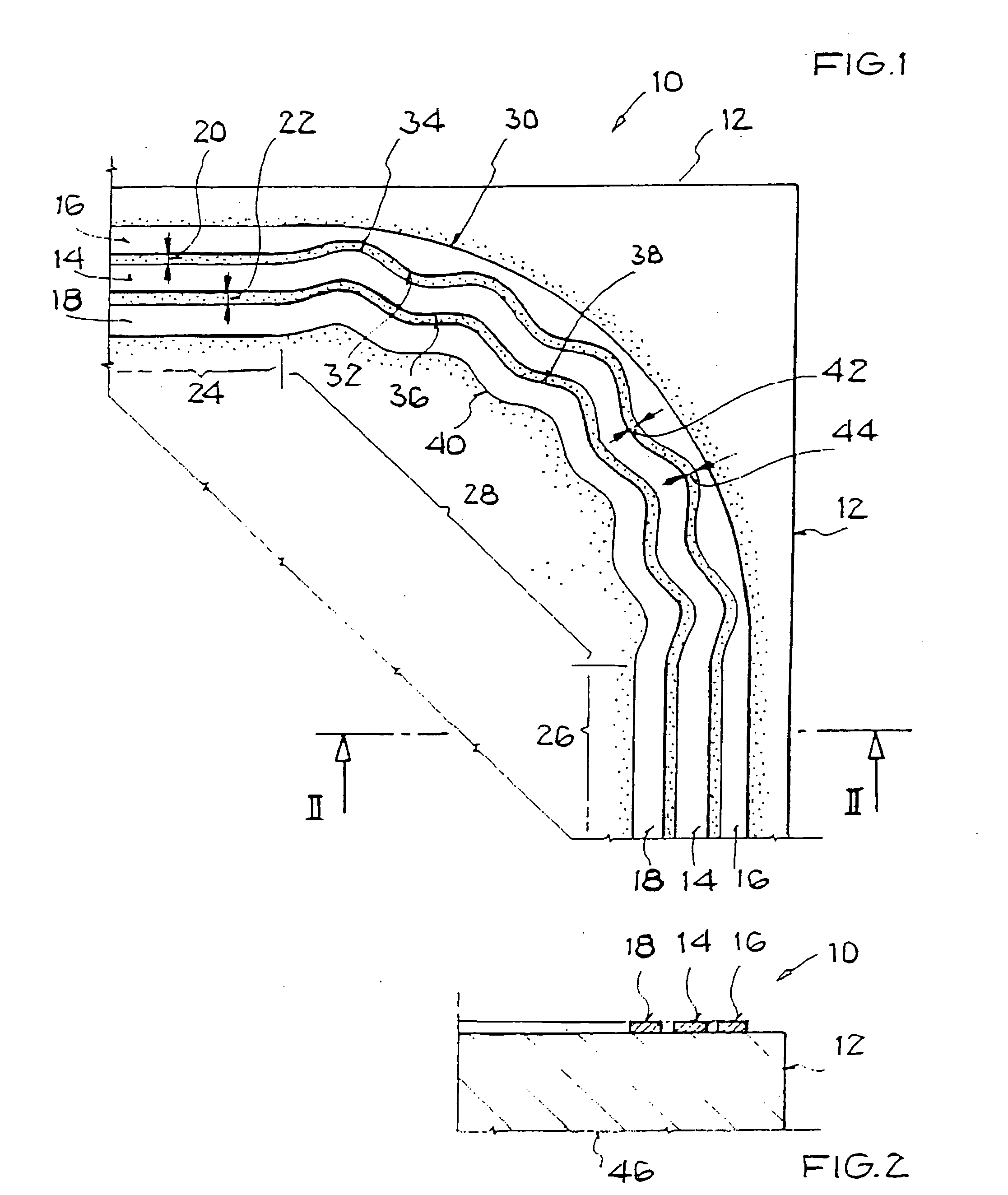
[0035]FIG. 1 shows a planar microwave line 10 in detail, which extends to a dielectric substrate 12 and has a first microstrip conductor 14 and two additional microstrip conductors 16 and 18. FIG. 1 thereby shows a coplanar line as microwave line 10. The coplanar line corresponds to a planar coaxial line. A first gap 20 between the first microstrip conductor 14 and a second microstrip conductor 16 as an additional microstrip conductor is dimensioned in such a way that during the transmission of microwaves an electromagnetic coupling occurs between the first microstrip conductor 14 and the second microstrip conductor 16. Analogously, a second gap 22 between the first microstrip conductor 14 and a third microstrip conductor 18 as an additional microstrip conductor is dimensioned in such a way that during the transmission of microwaves, an electromagnetic coupling occurs between the first microstrip conductor 14 and the third microstrip conductor 18.

[0036] The first microstrip conduct...


PUM


Abstract

A planar microwave line is provided, having a dielectric substrate and a planar arrangement of a first microstrip conductor and at least one additional microstrip conductor, in which a gap between the first microstrip conductor and the additional microstrip conductor permits an electromagnetic coupling, a first region in which the microwave line has a first direction, a second region in which the microwave line has a second direction, and a transition region in which a change from the first direction to the second direction occurs. The microwave line is characterized in that the adjacent edges of the first microstrip conductor and of the additional microstrip conductor in the transition region are equal in length and do not cross.

Description

[0001] This nonprovisional application claims priority under 35 U.S.C. §119(a) on German Patent Application Nos. DE 10200538456.0 and DE 102004053517.5, which were filed in Germany on Aug. 3, 2005 and Oct. 29, 2004, respectively, and which are herein incorporated by reference. BACKGROUND OF THE INVENTION [0002] 1. Field of the Invention [0003] The present invention relates to a planar microwave line having a dielectric substrate and a planar arrangement of a first microstrip conductor and at least one additional microstrip conductor, in which a gap between the first microstrip conductor and the additional microstrip conductor permits an electromagnetic coupling, to a first region in which the microwave line has a first direction, to a second region, in which the microwave line has a second direction, and to a transition region in which a change from the first direction to the second direction occurs. The invention relates further to a method for guiding a microwave, which propagates...

Claims


Application Information

Patent Timeline
IPC IPC(8): H01P5/18
CPCH01P1/02H01P3/003H01P5/185
Inventor ZIMMERLING, DETLEF
Owner ATMEL CORP
Why Eureka
Try Eureka