Method for manufacturing a stitched "floating" trailing shield for a perpendicular recording head

Inactive Publication Date: 2006-05-04
HITACHI GLOBAL STORAGE TECH NETHERLANDS BV
View PDF15 Cites 28 Cited by
  • Summary
  • Abstract
  • Description
  • Claims
  • Application Information

AI Technical Summary

Benefits of technology

[0019] Before depositing the seed layer, a layer of non-magnetic, electrically insulating material can be deposited and chemical mechanically polished to form a fill layer having a smooth planar upper surface that is coplanar with the upper surf

Problems solved by technology

These design parameters make fabrication of the trailing shield increasingly difficult for higher density magnetic recording designs.
Maintaining such tight tolerances while constructing a shield with sufficient area (as viewed from the ABS) cannot be achieved with existing manufacturing techniques.
However, use of such a low wavelength limits the thickness of the photoresist

Method used


Image

  • Method for manufacturing a stitched "floating" trailing shield for a perpendicular recording head
  • Method for manufacturing a stitched "floating" trailing shield for a perpendicular recording head
  • Method for manufacturing a stitched "floating" trailing shield for a perpendicular recording head

Examples


Embodiment Construction

[0030] The following description is of the best embodiments presently contemplated for carrying out this invention. This description is made for the purpose of illustrating the general principles of this invention and is not meant to limit the inventive concepts claimed herein.

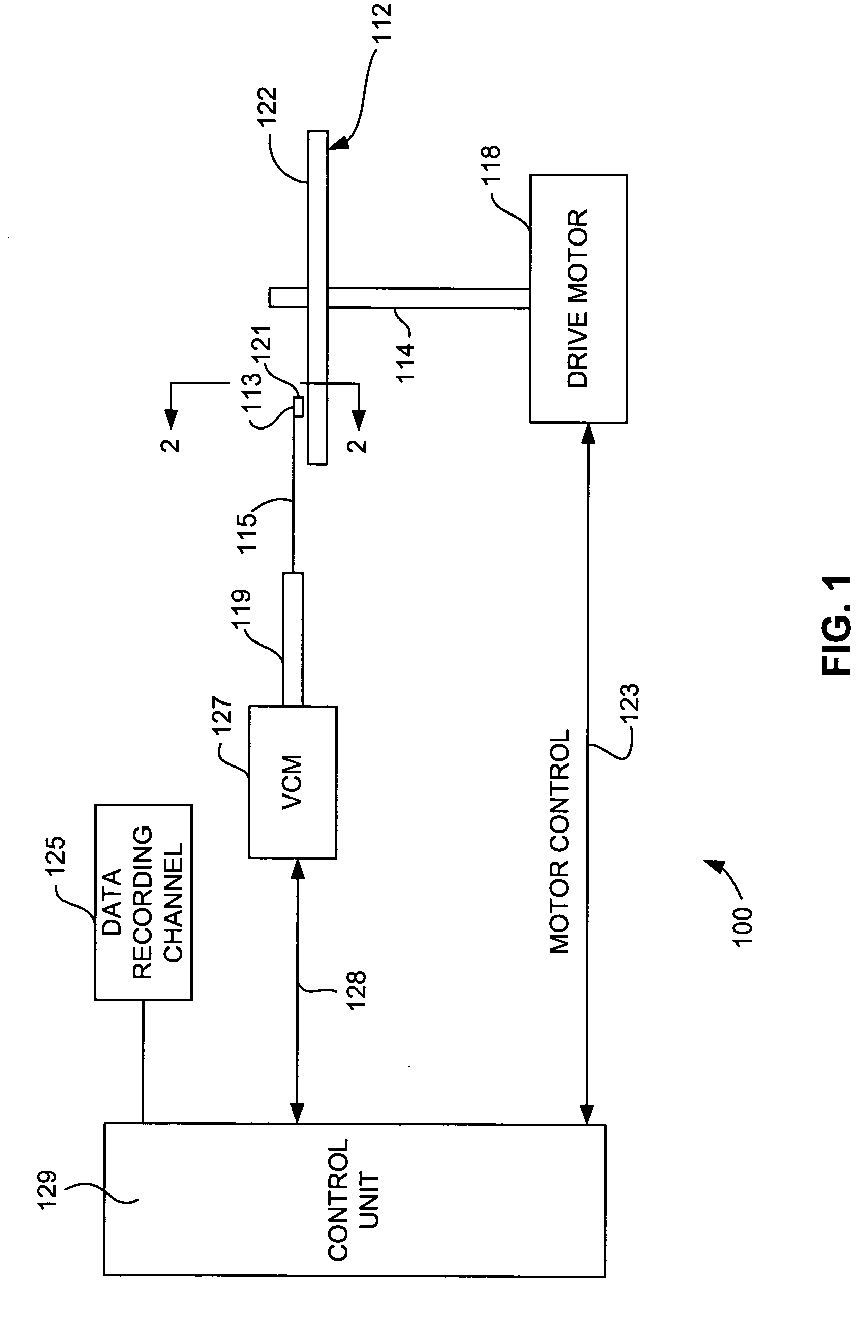
[0031] Referring now to FIG. 1, there is shown a disk drive 100 embodying this invention. As shown in FIG. 1, at least one rotatable magnetic disk 112 is supported on a spindle 114 and rotated by a disk drive motor 118. The magnetic recording on each disk is in the form of annular patterns of concentric data tracks (not shown) on the magnetic disk 112.

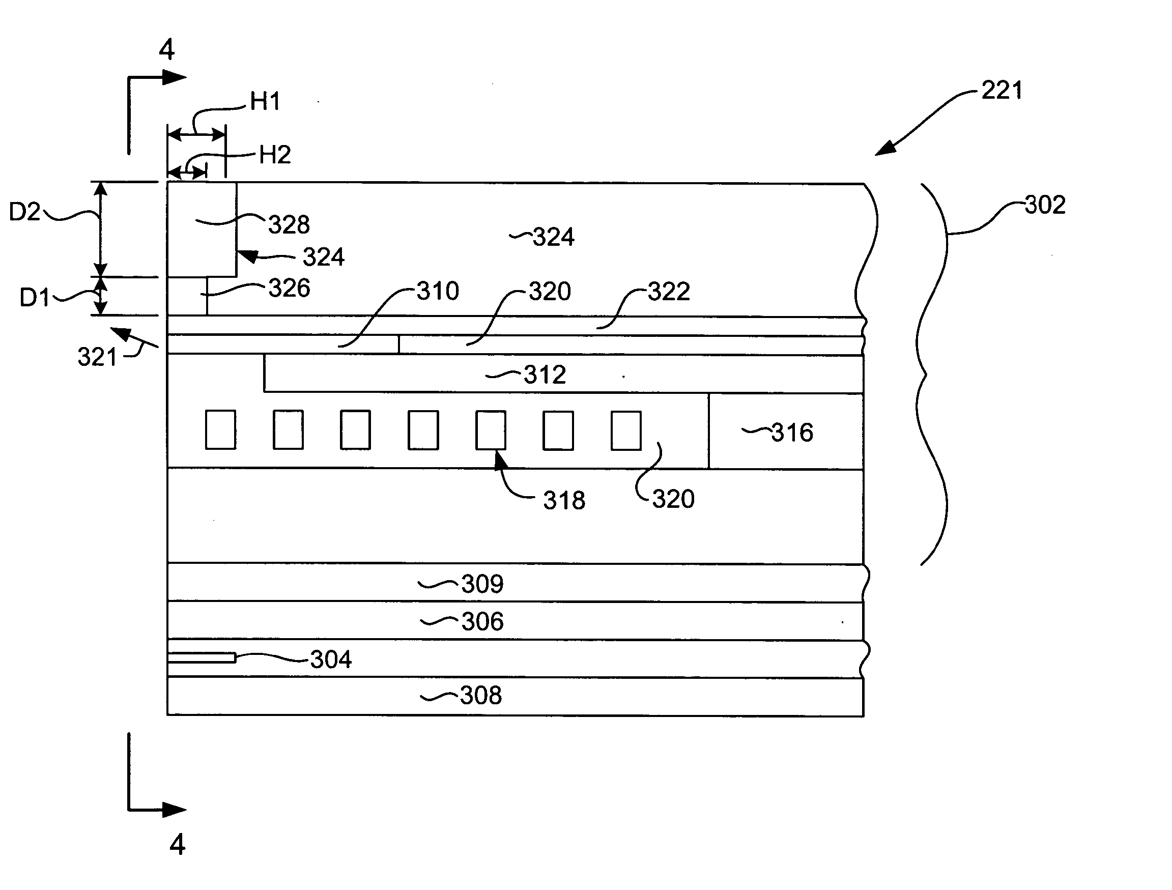
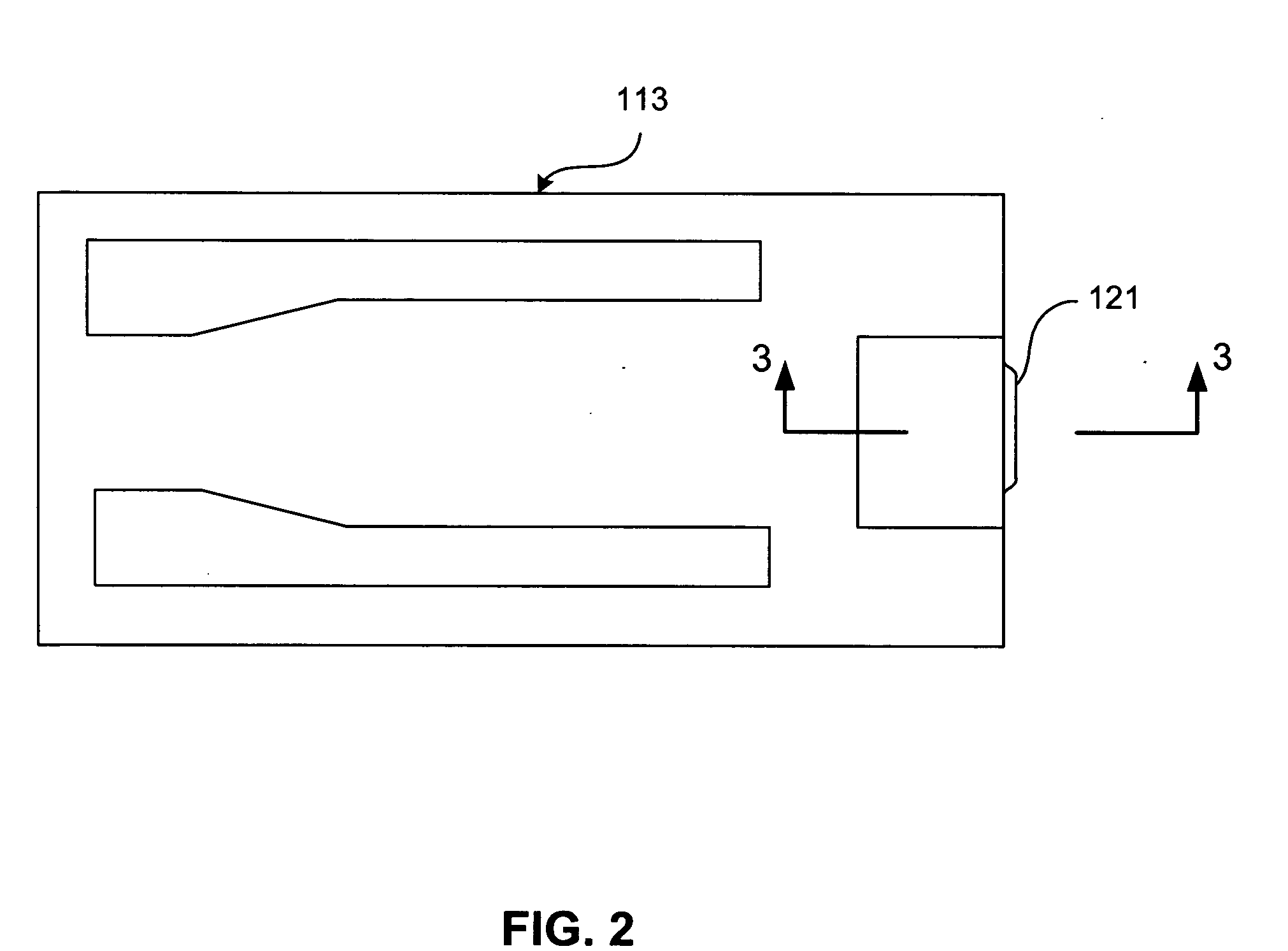
[0032] At least one slider 113 is positioned near the magnetic disk 112, each slider 113 supporting one or more magnetic head assemblies 221. As the magnetic disk rotates, slider 113 moves radially in and out over the disk surface 122 so that the magnetic head assembly 121 may access different tracks of the magnetic disk where desired data are written. Each sli...


PUM

PropertyMeasurementUnit
Thicknessaaaaaaaaaa
Nanoscale particle sizeaaaaaaaaaa
Wavelengthaaaaaaaaaa

Abstract

A bi-layer, floating, trailing shield for use in a perpendicular magnetic recording system and a method for manufacturing such a trailing shield. Manufacturing the trailing shield as a bilayer trailing shield allows certain critical alignments to be maintained during lithography and allows high resolution photolithographic procedures to be used by allowing the use of a thinner resist, especially during construction of the first layer of the bilayer trailing shield structure. A trailing shield according to an embodiment of the invention improves magnetic performance of the write head by canting the magnetic write field from the write pole.

Description

FIELD OF THE INVENTION [0001] The present invention relates to perpendicular magnetic recording and more particularly to a novel trailing magnetic shield design and a method for manufacturing such a shield design. BACKGROUND OF THE INVENTION [0002] The heart of a computer's long term memory is an assembly that is referred to as a magnetic disk drive. The magnetic disk drive includes a rotating magnetic disk, write and read heads that are suspended by a suspension arm adjacent to a surface of the rotating magnetic disk and an actuator that swings the suspension arm to place the read and write heads over selected circular tracks on the rotating disk. The read and write heads are directly located on a slider that has an air bearing surface (ABS). The suspension arm biases the slider toward the surface of the disk, and when the disk rotates, air adjacent to the disk moves along with the surface of the disk. The slider flies over the surface of the disk on a cushion of this moving air. W...

Claims


Application Information

Patent Timeline
IPC IPC(8): G11B5/147
CPCG11B5/1278Y10T29/49046G11B5/3163
Inventor LE, QUANG
Owner HITACHI GLOBAL STORAGE TECH NETHERLANDS BV
Why Eureka
Try Eureka