
Optical transponder having switching function

a technology of optical transponders and functions, applied in data switching networks, wavelength-division multiplex systems, multiplex communication, etc., can solve the problems of reducing the flexibility of network utilization, requiring a lot of time, and conventional optical transponders without switching functions

Inactive Publication Date: 2006-05-04
ELECTRONICS & TELECOMM RES INST
View PDF9 Cites 11 Cited by
  • Summary
  • Abstract
  • Description
  • Claims
  • Application Information

AI Technical Summary

Problems solved by technology

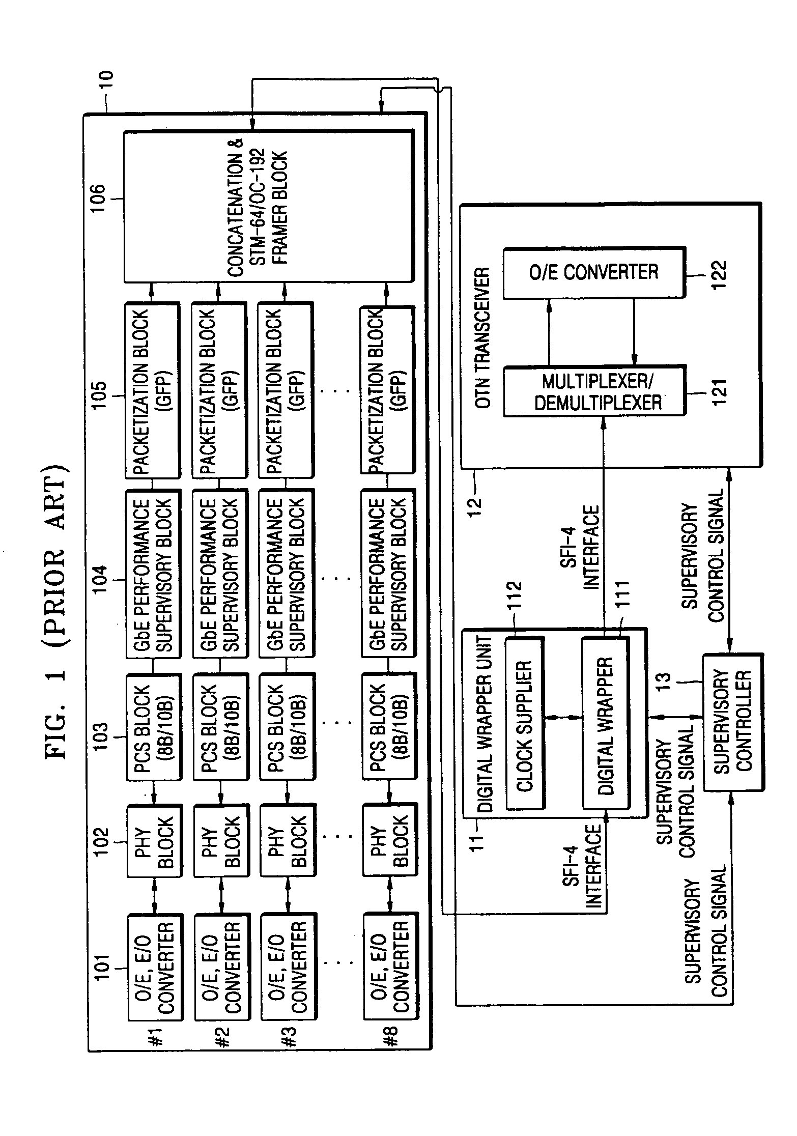
However, a conventional optical transponder does not have a switching function required for the GbE signal to change a transmission route of the signal with respect to each multiplexed channel (port).
Such a fixed operation causes inconvenience in that an operator has to change the transmission route personally when a network configuration needs a change in the transmission route.
This operation takes a lot of time, thereby degrading the flexibility of network utilization.

Method used


Image

  • Optical transponder having switching function
  • Optical transponder having switching function
  • Optical transponder having switching function

Examples


Embodiment Construction

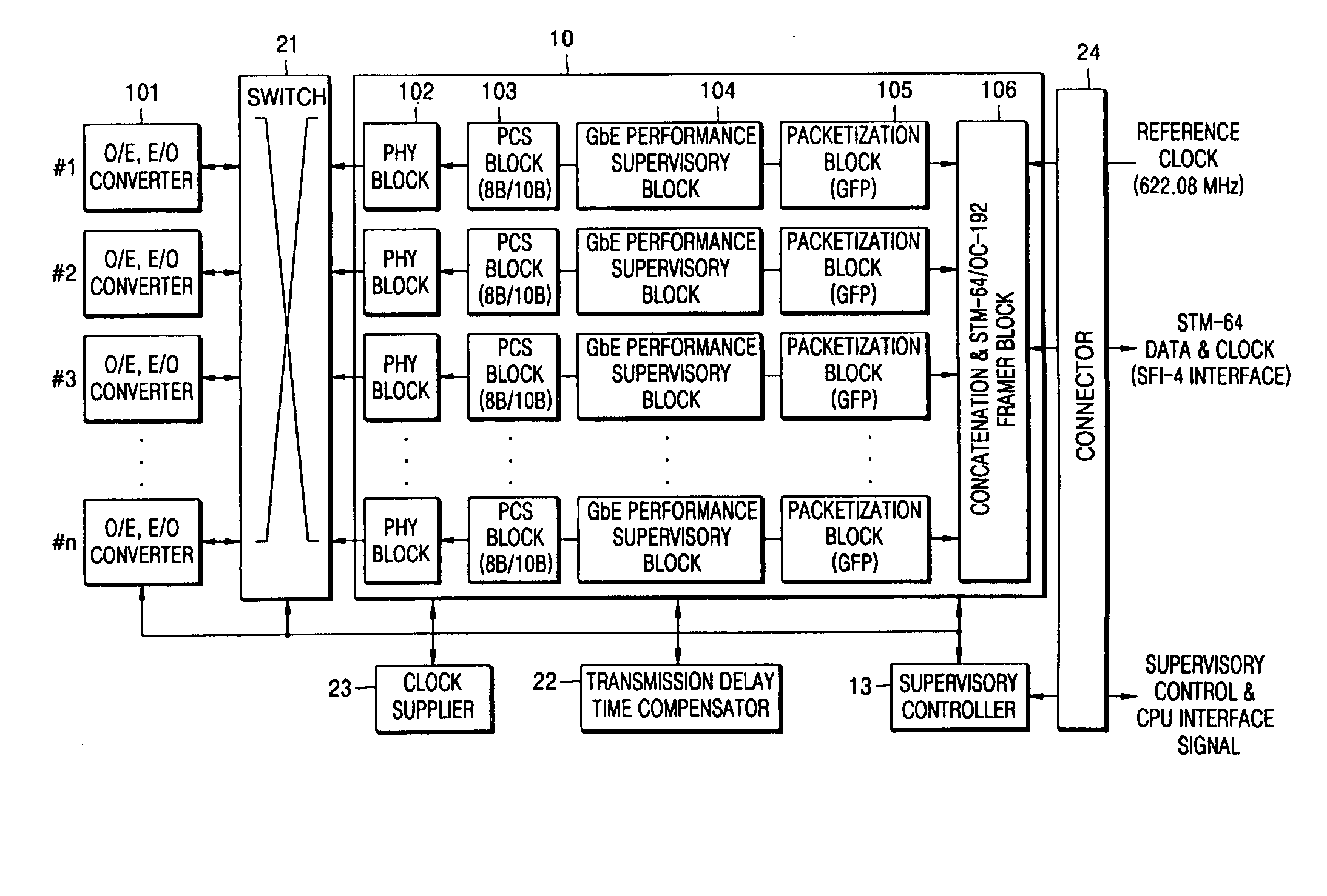
[0017] The present invention will now be described more fully with reference to the accompanying drawings, in which exemplary embodiments of the invention are shown. The invention may, however, be embodied in many different forms and should not be construed as being limited to the embodiments set forth herein; rather, these embodiments are provided so that this disclosure will be thorough and complete, and will fully convey the concept of the invention to those skilled in the art. Like reference numerals in the drawings denote like elements.

[0018]FIG. 1 is a block diagram illustrating a conventional optical transponder that multiplexes a GbE (Gigibit Ethernet) signal. Referring to FIG. 1, the conventional optical transponder that has no switching function and receives a GbE optical signal comprises a GbE interface unit 10 for mapping the GbE optical signal to an STM-64 / OC-192 signal or mapping the STM-64 / OC-192 signal to the GbE optical signal, a digital wrapper unit 11 for mapping...


PUM


Abstract

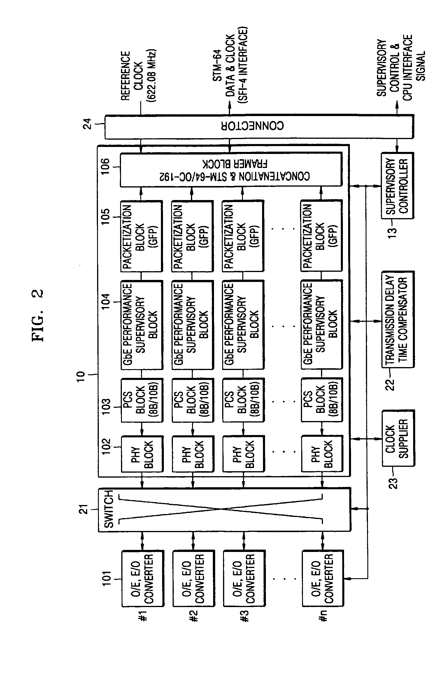
Provided is an optical transponder that receives a tributary signal such as a SDH / SONET signal, a GbE (Gigibit Ethernet) signal, and a SAN (Storage Area Network) signal in a WDM (Wavelength Division Multiplexing) transmission system and a SDH (Synchronous Digital Hierarchy) / SONET (Synchronous Optical Network) system, and more particularly, to an optical transponder having a switching function. The optical transponder having a switching function includes: a switch changing a data path of an input tributary signal from a plurality of channels (ports); an STM-64 / OC-192 mapper / demapper mapping the tributary signal switched to a different data path by the switch to an STM-64 / OC-192 signal or demapping the STM-64 / OC-192 signal to the tributary signal; and a transmission delay time compensator compensating for a differential delay caused by a transmission route difference on an optical fiber link when the STM-64 / OC-192 signal is demapped to the tributary signal.

Description

[0001] This application claims the benefit of Korean Patent Application Nos. 10-2004-0088179, filed on Nov. 2, 2004 and 10-2005-0007248, filed on Jan. 26, 2005, in the Korean Intellectual Property Office, the disclosures of which are incorporated herein in its entirety by reference. BACKGROUND OF THE INVENTION [0002] 1. Field of the Invention [0003] The present invention relates to an optical transponder that receives a tributary signal such as an SDH / SONET signal, a GbE (Gigibit Ethernet) signal, and an SAN (Storage Area Network) signal in a WDM (Wavelength Division Multiplexing) transmission system and an SDH (Synchronous Digital Hierarchy) / SONET (Synchronous Optical Network) system, and more particularly, to an optical transponder having a switching function. [0004] 2. Description of the Related Art [0005] An optical transponder interconnects a WDM transmission system and an SDH / SONET system with a client network. The optical transponder has been used to receive an SDH / SONET sign...

Claims


Application Information

Patent Timeline
IPC IPC(8): H04J3/02
CPCH04J3/062H04J3/1617H04J14/02H04J2203/0094
Inventor LEE, JOON KILEE, JYUNG CHANKIM, KWANGJOON
Owner ELECTRONICS & TELECOMM RES INST
Learn More