

Multimode long period fiber Bragg grating machined by ultrafast laser direct writing
a technology of laser direct writing and optical fiber, which is applied in the direction of cladded optical fibre, semiconductor laser, instruments, etc., can solve the problems of unsatisfactory effects, undesirable non-linearities, and the requirement that the optical fiber have a photosensitive cor
- Summary
- Abstract
- Description
- Claims
- Application Information
AI Technical Summary
Benefits of technology
Problems solved by technology
Method used
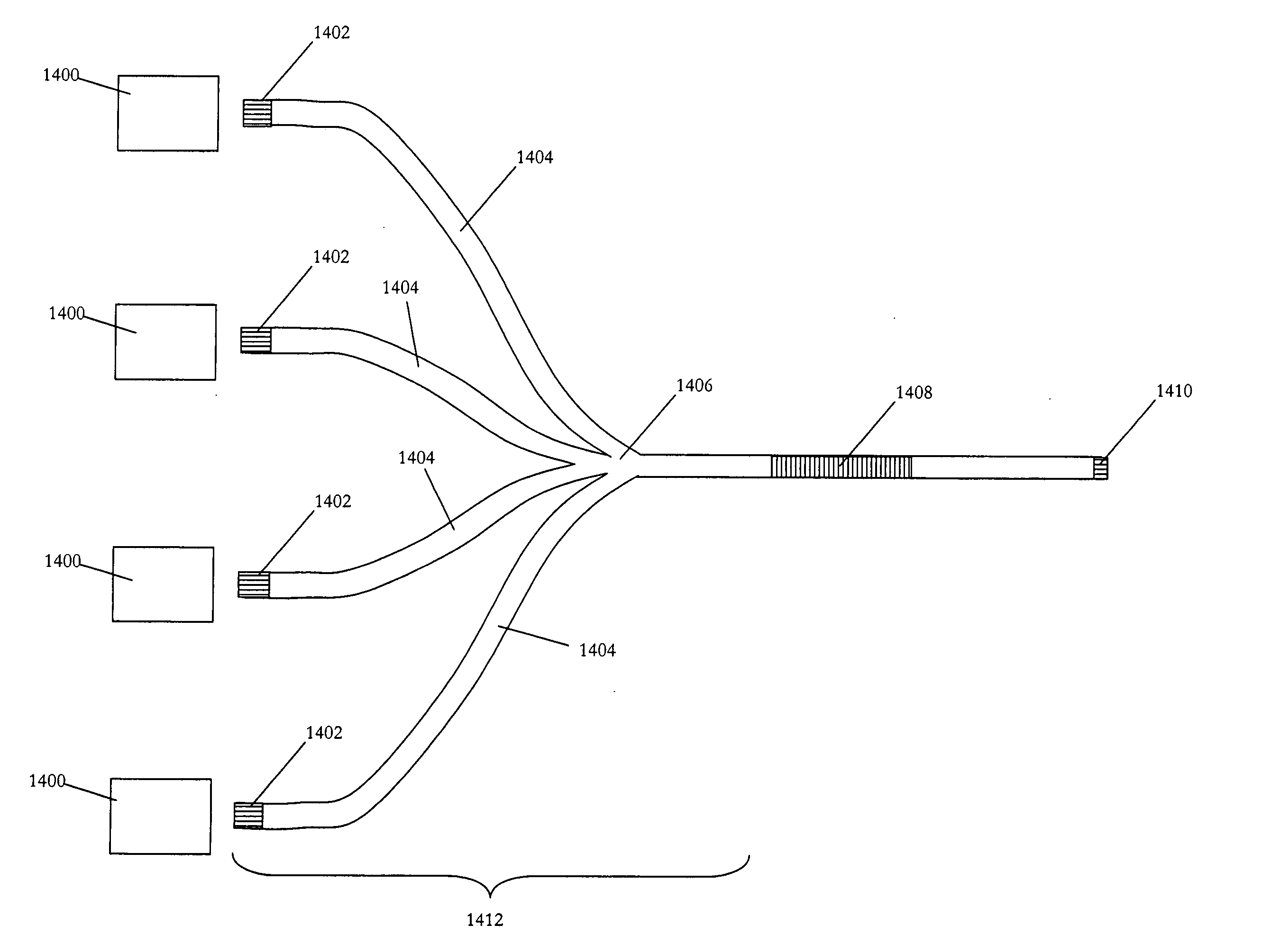
Image

Examples
Embodiment Construction
[0050] The extremely high intensities achievable in ultrafast laser machining of materials allow the material to be changed in a number of ways. The most common way that a material may be changed during ultrafast laser machining is for the material to be removed from the surface via ablation. Alternatively, various properties of the material may be changed such as the crystallinity and / or the refractive index. These material changes may occur on the surface of the material or, for substantially transparent materials, the ultrafast pulses may be focused within the material to cause these changes to take place inside of the bulk of the material. These internal changes may occur only above a specific fluence, so that the intervening material may be unaffected by the ultrafast laser pulses. Careful control of the pulse energy, pulse duration, and focus of the pulses may allow for the creation of precise regions with changed properties that have sharp boundaries.
[0051] Thus, the use of ...
PUM
 Abstract
Description
Claims
Application Information