Microfluidic system

a microfluidic and system technology, applied in the field of microfluidics, can solve the problems of high cost of system operation, difficult handling of nanoliter volumes of membrane proteins, and affecting the efficiency of the system, so as to achieve rapid and economical reactions

Active Publication Date: 2006-05-04
CHICAGO UNIV OF
View PDF17 Cites 274 Cited by
  • Summary
  • Abstract
  • Description
  • Claims
  • Application Information

AI Technical Summary

Benefits of technology

[0007] This invention provides a method of conducting a large number of reactions in parallel, such as crystallizations or assays, allowing rapid and economical reactions.

Problems solved by technology

Crystals of membrane proteins are often fragile and can be damaged by handling, therefore technologies are needed to allow for direct in situ testing of the diffraction quality of crystals.
Handling nanoliter volumes of solutions of membrane proteins is challenging due to their high viscosity and low surface tension.
Unfortunately, this system is expensive to operate; the combinatorially mixing chips are significantly more expensive than traditional crystallography plates; the combinatorially mixing chips are water and gas permeable; and are incompatible with organic solvents.

Method used


Image

  • Microfluidic system
  • Microfluidic system
  • Microfluidic system

Examples


example 1

No-Loss Injection of Sub-μL Volumes of Solutions into Microfluidic Devices

[0187] A 10 μL syringe and a piece of Teflon tubing were filled with the perfluoroamine, followed by aspiration of a small volume (less than 1 μL) of a membrane protein solution. Because the perfluoroamine carrier fluid preferentially wet the Teflon, it formed a thin layer between the protein and Teflon, preventing sticking of the protein solution to the walls of the tubing and allowed for complete, no-loss dispensing into a microfluidic device.

example 2

Forming an Array of Plugs of Different Composition in a Holding Component

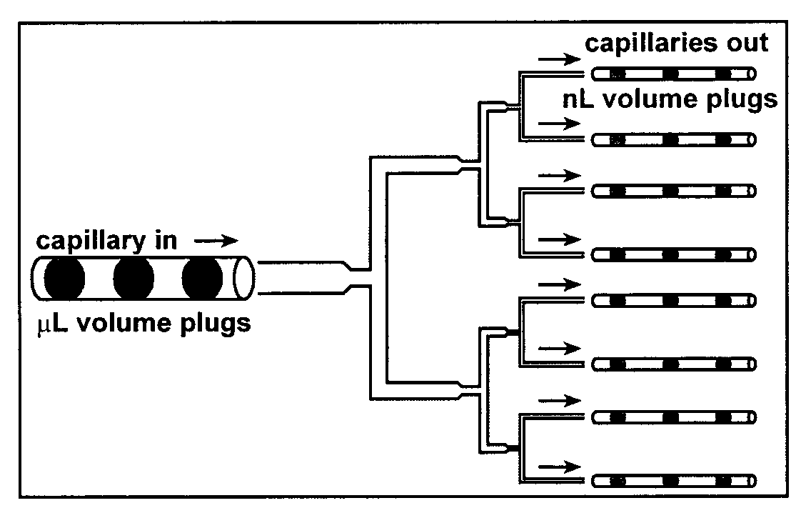
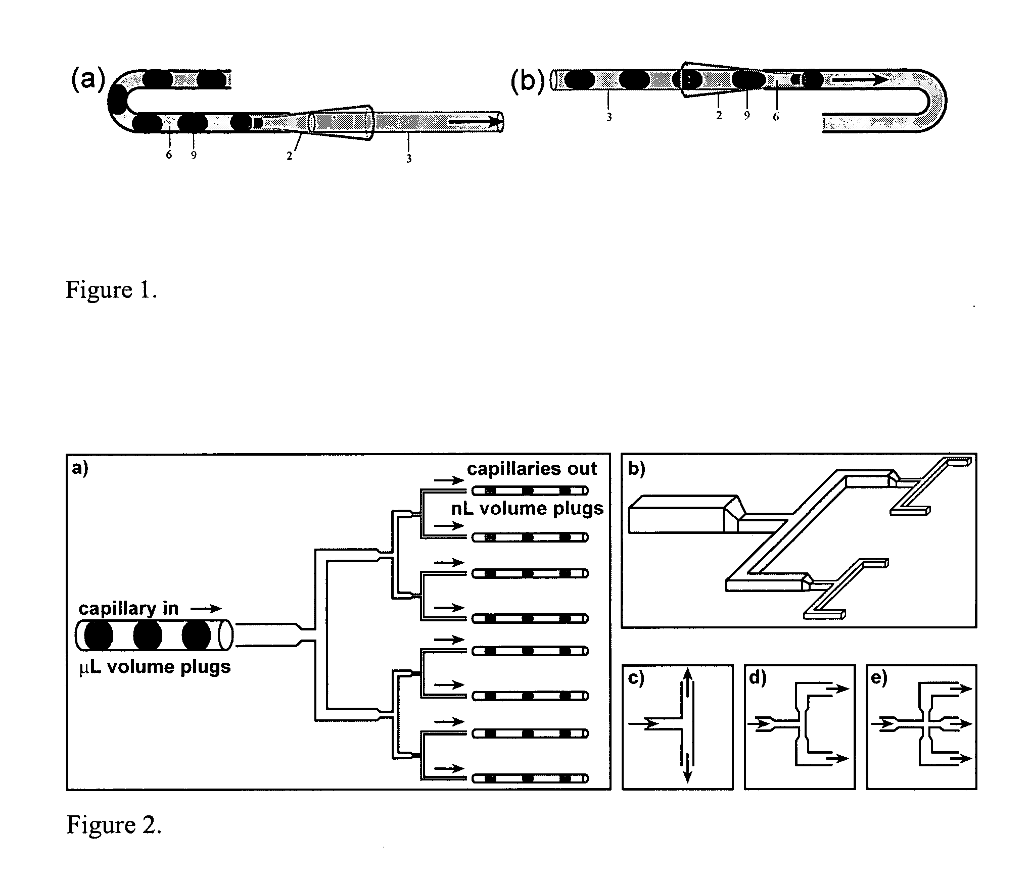
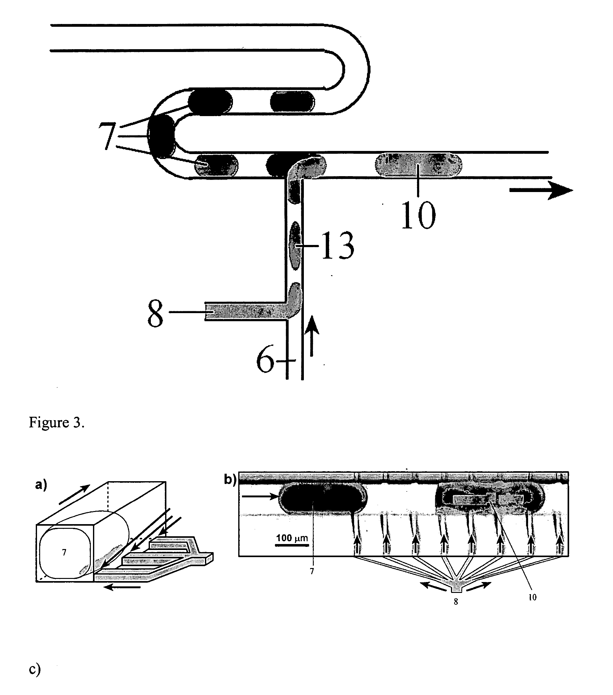
[0188] In this experiment, array of plugs containing different composition were generated in Teflon tubing or in glass capillaries. A piece of Teflon tubing (OD: 760 μm, ID: 305 μm) was attached to the needle of a 5 μL syringe (Hamilton). Another piece of Teflon tubing with smaller diameter (OD: 250 μm, ID: 200 μm) was attached to the large Teflon tubing and sealed by either epoxy or wax. Oil (FC-3283 / PFO at 50:1) was aspirated into the tubing and the syringe. The tubing was immersed into an aqueous solution of composition A (solution A), and the plunger was pulled back to aspirate a small amount (0.1-0.5 μL) of solution A. Next the tubing was immersed into the oil and the same amount of oil was aspirated into the tubing. This two-step aspiration process was repeated for solution B, C, . . . until all the solutions were used, and an array of plugs of composition of A, B, . . . was formed inside the Teflon tubi...

example 3

Transporting the Array of the Plugs into a PDMS Microchannel

[0191] In this experiment, the array of the plugs stored inside the Teflon tubing or the glass capillary (holding component) was transported into a PDMS microchannel (receiving component).

[0192] Three different configurations were used. In the first configuration, the inlet of the PDMS microchannel was coupled to a glass capillary obtained from Hampton research. This capillary was used as an adapter and it had a shape of a funnel. The small end of the capillary was inserted into the PDMS microchannel and the gap between the capillary and the wall of the PDMS microchannel was filled with half-cured PDMS. After incubation at 110° C. for 5 min, the half-cured PDMS was solidified and the junction became leak-proof. The capillary that had the array of the plugs inside was firmly inserted into the larger end of the adapter capillary. The connection was leak-proof without any sealing. By tilting the whole setup, the gravity forc...


PUM


Abstract

The present invention provides microfluidic technology enabling rapid and economical manipulation of reactions on the femtoliter to microliter scale.

Description

RELATED APPLICATIONS [0001] The present application is related to and claims priority pursuant to 35 USC 119 to U.S. Provisional Patent Application Ser. No. 60 / 623,261, filed Oct. 29, 2004, which is incorporated herein by reference.FEDERALLY SPONSORED RESEARCH OR DEVELOPMENT [0002] This work was supported by the NIH (R01 EB001903). Additionally, some of this work was performed at the MRSEC microfluidic facility funded by the NSF. The government may have certain rights in this application.TECHNICAL FIELD [0003] The present invention relates to the field of microfluidics. This invention provides microfluidic technology enabling rapid and economical manipulation of reactions on the sub-femtoliter to milliliter scale. BACKGROUND OF THE INVENTION [0004] The ability to run a large number of reactions using minimal reagent is desirable. Various solutions to this goal have been proposed, including robotics, microfluidics, combinatorial chemistry in 96-well plates, etc. The application of th...

Claims


Application Information

Patent Timeline
Patent Type & Authority Applications(United States)
IPC IPC(8): B01L3/00
CPCB01F13/0071Y10T436/12B01L3/502723B01L3/502784B01L3/527B01L2200/0673B01L2300/0816B01L2300/0864B01L2300/0867B01L2400/0406B01L2400/0409B01L2400/0415B01L2400/0433B01L2400/0487C30B7/00C30B29/58G01N35/08B01L3/06B01F33/3021
Inventor ISMAGILOV, RUSTEM F.ZHENG, BOGERDTS, CORY J.
Owner CHICAGO UNIV OF
Why Eureka
Try Eureka