
Socket contact

a socket connector and socket technology, applied in the field of socket connectors, can solve the problems of generating heat exceeding the regulated temperature of 30° c, difficult to realize a socket connector with a further lowered height in a conventional socket connector, and inapplicability, so as to reduce stress concentration, reduce the effect of generation of deformation and reduced siz

Active Publication Date: 2006-05-04
JST MFG CO LTD
View PDF5 Cites 15 Cited by
  • Summary
  • Abstract
  • Description
  • Claims
  • Application Information

AI Technical Summary

Benefits of technology

[0029] The socket contact according to the present invention can apply a stronger contact force to the opposing contact than a conventional socket contact, and furthermore, can be more miniaturized than the conventional socket contact. This is because the socket contact according to the present invention is structured such that the conventional tuning fork-type contact has two stages. In addition, the socket contact according to the present invention can be aligned in parallel, even in narrow pitch.
[0033] Stress is thought to be dispersed in the arcuate connection part, lowering stress concentration, by forming the tips of the pair of reversed arms into a smooth shape wherein they are connected to each other arcuately, when the opposing contact is inserted into the pair of reversed arms. Generation of deformation is thought to be suppressed by allowing the tips of the pair of reversed arms to be an arcuate connection part.
[0042] Because the contact connection part connected to the opposing contact is provided with a pair of extended arms and a pair of reversed arms, whose longitudinal shape is U-shaped by folding back and reversing the base-end side of the contact body, wherein the tips of this pair of reversed arms are joined, and also provided with a pair of contact points on the reversed arms, wherein the pair of contact points are designed such as to apply contact force to both surfaces of the opposing contact, the socket contact according to the present invention can apply a contact force which is stronger than that of conventional socket contact to the opposing contact and can made smaller than the conventional socket contact, as well. The socket contact according to the present invention can be aligned in parallel, even in narrow pitch.
[0043] Furthermore, stress is thought to be dispersed in the arcuate connection part, lowering stress concentration, and generation of deformation is thought to be suppressed, by forming the tips of the pair of reversed arms into a smooth shape wherein they are connected arcuately, when the opposing contact is inserted into the pair of reversed arms.

Problems solved by technology

Although socket contact 9 shown in FIG. 11 can handle, for example, rated voltage 50V and rated current “1” A (ampere), there are requests for rated current of 2 A. However, if a current of 2 A is allowed to flow into connector 100, the connector, for example, generates heat exceeding the regulated temperature of 30° C., which is not practical.
It is difficult to realize a socket connector with a further lowered height in a conventional socket contact.
In other words, in the tuning fork-type contact, it is difficult to realize a socket connector suitable for high-density mounting, even if contact force can be secured.
In addition, there is concern that residual stress, accompanying the crimping process performed on an open crimp barrel when a so-called bellows-type two-way contact and the tuning fork-type contact shown FIG. 10 and FIG. 11 are both crimp contacts to which the lead wire is crimped, may affect the pair of contact pieces (arms), the tips of which are opened.
For example, there is concern that the distance between the pair of contact points may vary with long-term deterioration.

Method used


Image

  • Socket contact
  • Socket contact
  • Socket contact

Examples


Embodiment Construction

[0055] The preferred embodiment of the present invention is described below, with reference to the drawings.

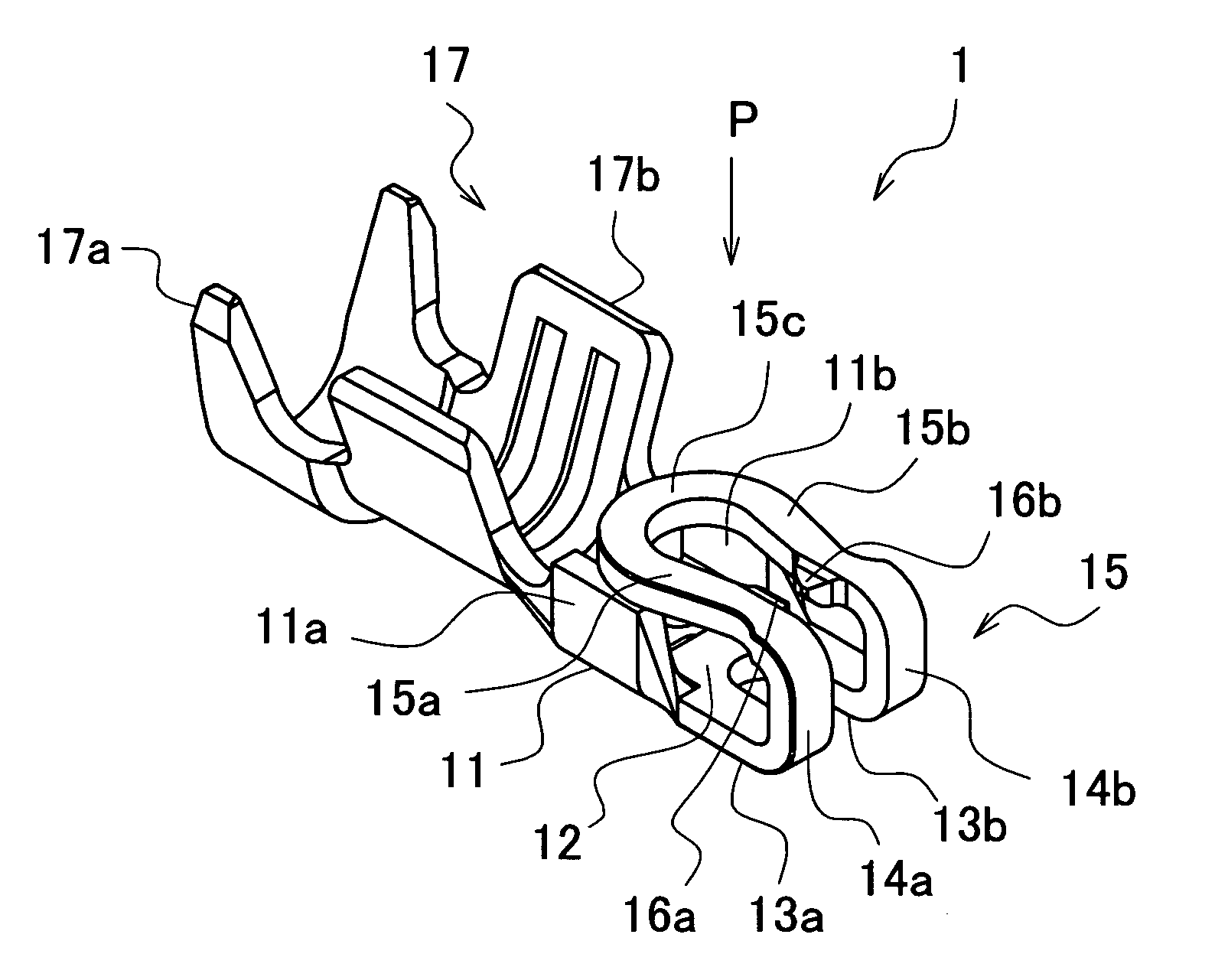
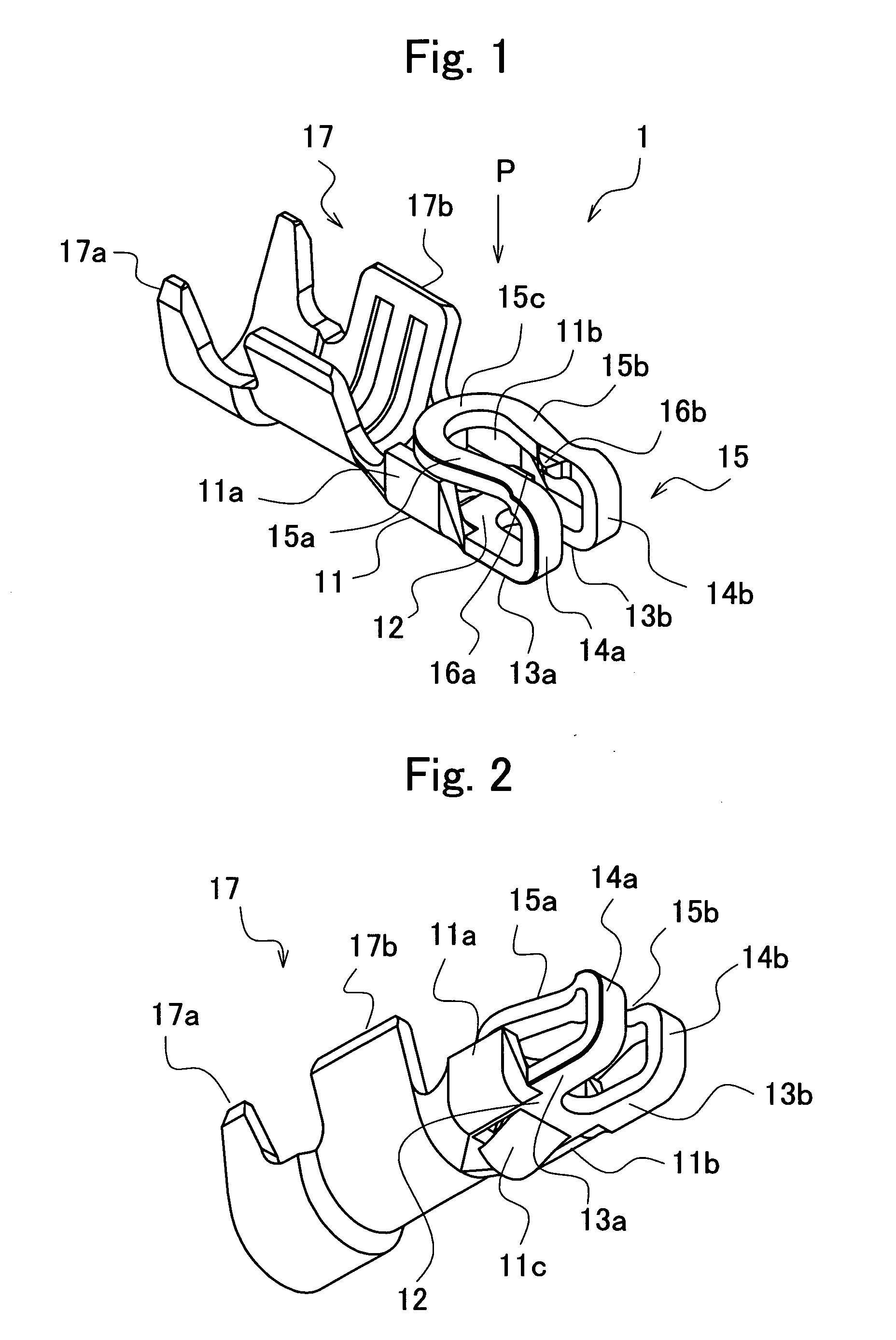
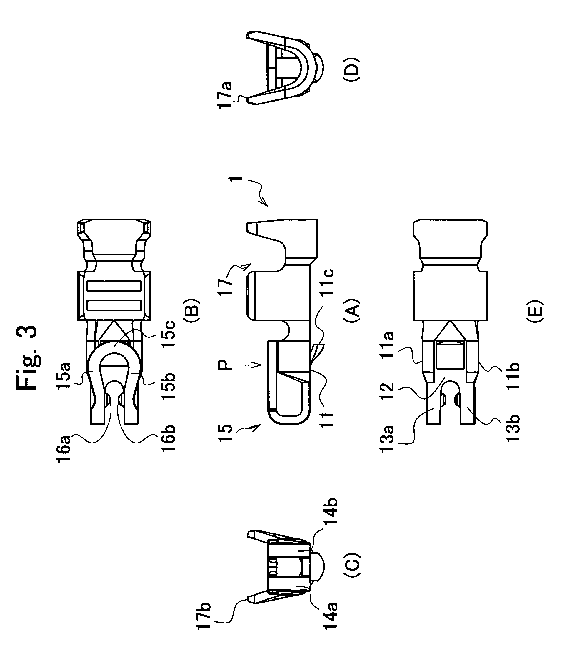
[0056]FIG. 1 is a perspective outline view showing one embodiment of a socket contact according to the present invention. FIG. 2 is a perspective outline view of the socket contact according to this embodiment. FIG. 2 shows the socket contact from the side opposite of that in FIG. 1. FIG. 3 is an outline view of the socket contact according to the embodiment. FIG. 3(A) is a front view, FIG. 3(B) is a top view, FIG. 3(C) is a left-side view, FIG. 3(D) is a right-side view and FIG. 3(E) is a bottom view.

[0057]FIG. 4 is a perspective outline view of a socket connector to which the socket contact according to the embodiment is applied. FIG. 5 is a perspective outline view of the socket connector to which the socket contact according to the embodiment is applied. FIG. 5 shows the socket connector from the side opposite of that in FIG. 4. FIG. 6 is a perspective outline view of a ...


PUM


Abstract

A socket contact which is connected to an opposing planar contact, comprises: a long connection part to which a lead wire is connected; and a contact connection part which is connected to the opposing contact provided on the base-end side of the connection part. The contact connection part comprises a planar contact body, a pair of extended arms which are almost parallel and extends from the base-end side of the contact body, and a pair of reversed arms which are almost parallel and extends from the tips of the pair of extended arms to the contact body, the tips of which are mutually joined. The pair of reversed arms are provided with a pair of contact points which are mutually opposed and into which opposing contacts can be inserted.

Description

FIELD OF THE INVENTION [0001] Priority is claimed on Japanese Patent Application No. 2004-317950, filed Nov. 1, 2004, the content of which is incorporated herein by reference. [0002] The present invention relates to a socket contact and, more particularly, to a socket contact which is a pair of elastic contact pieces that extend in parallel and apply contact force to both surfaces of an opposing, planar or straight-fluted contact. RELATED ART [0003] Batteries are embedded into modern, miniaturized mobile electronic devices such as, for example, DSC (Digital Still Camera), mobile telephones, CD players, MD players and the like. In order to feed power supply from this battery to a circuit substrate (printed circuit board) provided within the electronic device, an infinitesimal, so-called chip-sized package-type, wire-to-board connector is used. [0004] As the foregoing connector and socket connector, a connector has been invented which eliminates a problem of being easily broken, due t...

Claims


Application Information

Patent Timeline
Patent Type & Authority Applications(United States)
IPC IPC(8): H01R13/11
CPCH01R4/185H01R12/57H01R13/113H01R13/567H01R13/6273H01R12/75
Inventor MASAKI, KATSUYUKIKODAMA, SHINICHI
Owner JST MFG CO LTD
Learn More