
Digital interface receiver apparatus

a receiver and digital audio technology, applied in the field of digital interface receivers, can solve the problems of causing damage to the speaker, causing user unfavorable feelings, and generating audio noise in digital audio signals, and achieve the effect of easy recognition of errors

Active Publication Date: 2006-05-04
PANASONIC CORP
View PDF17 Cites 40 Cited by
  • Summary
  • Abstract
  • Description
  • Claims
  • Application Information

AI Technical Summary

Benefits of technology

[0014] It is an object of the present invention to provide a digital interface receiver in which audio noise disagreeable to a user is decreased.

Problems solved by technology

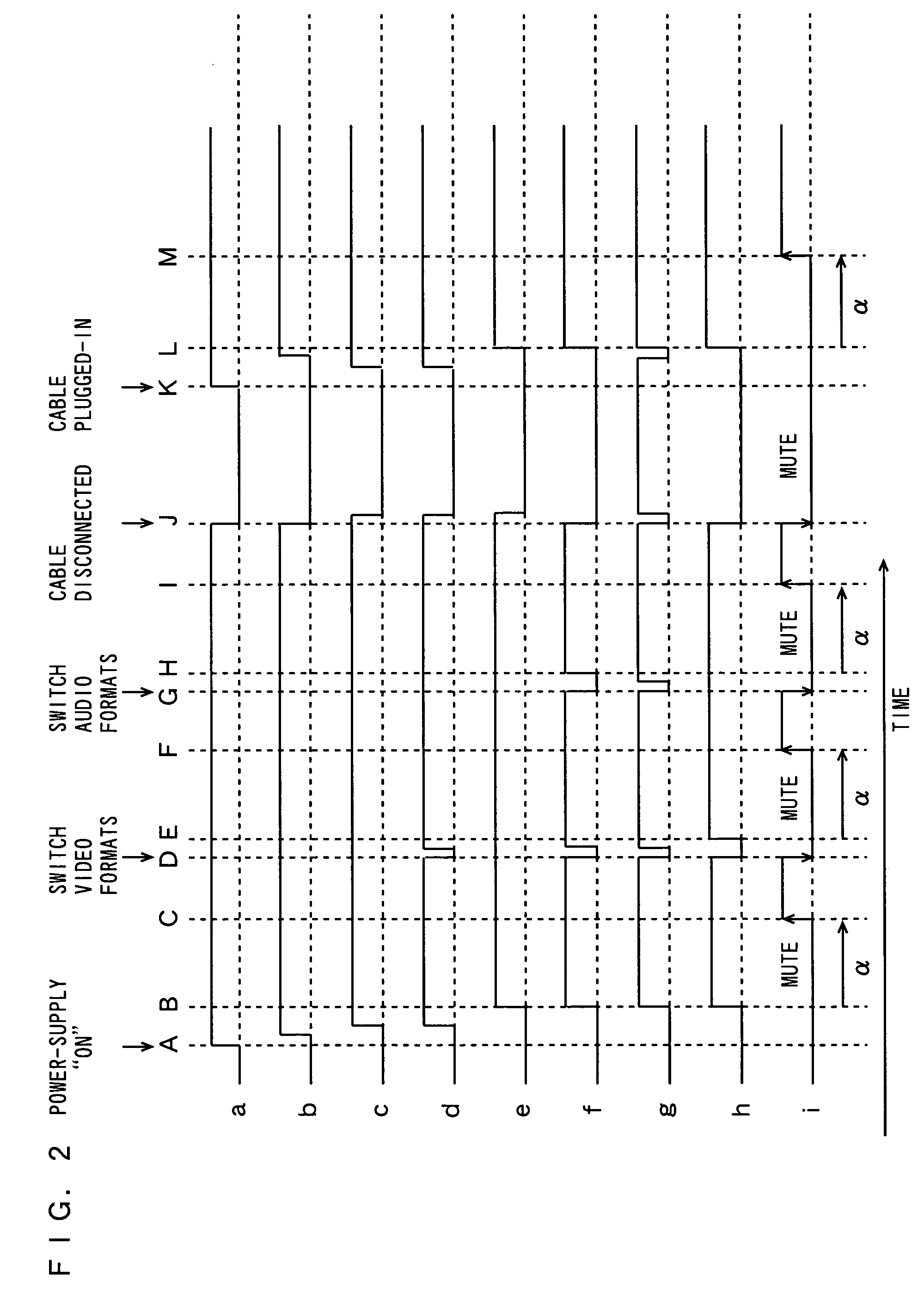
The transmission of the digital audio signal may generate audio noise due to cable disconnection or plugging in, transmission error, power-supply ON / OFF, or switching of video / audio formats, which gives a user a disagreeable feeling or damages the speaker.

Method used


Image

  • Digital interface receiver apparatus
  • Digital interface receiver apparatus
  • Digital interface receiver apparatus

Examples


Embodiment Construction

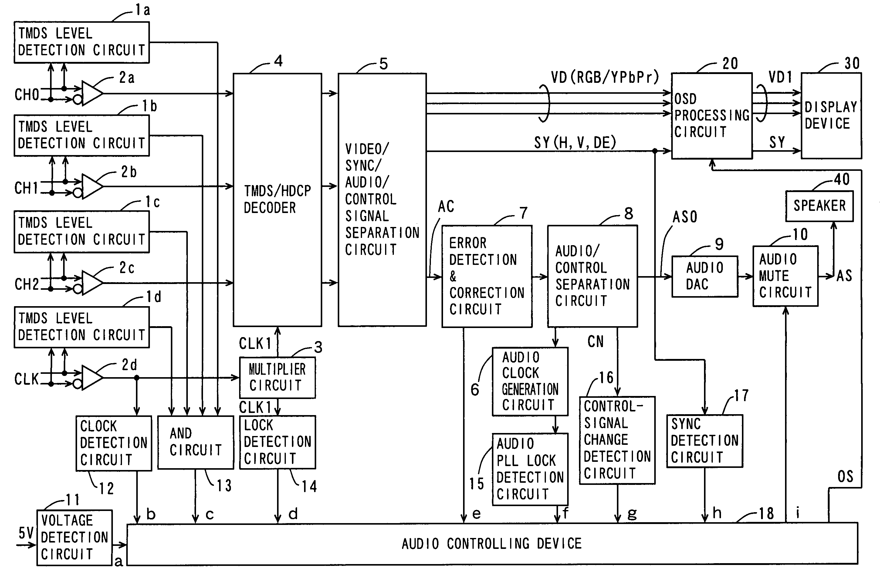
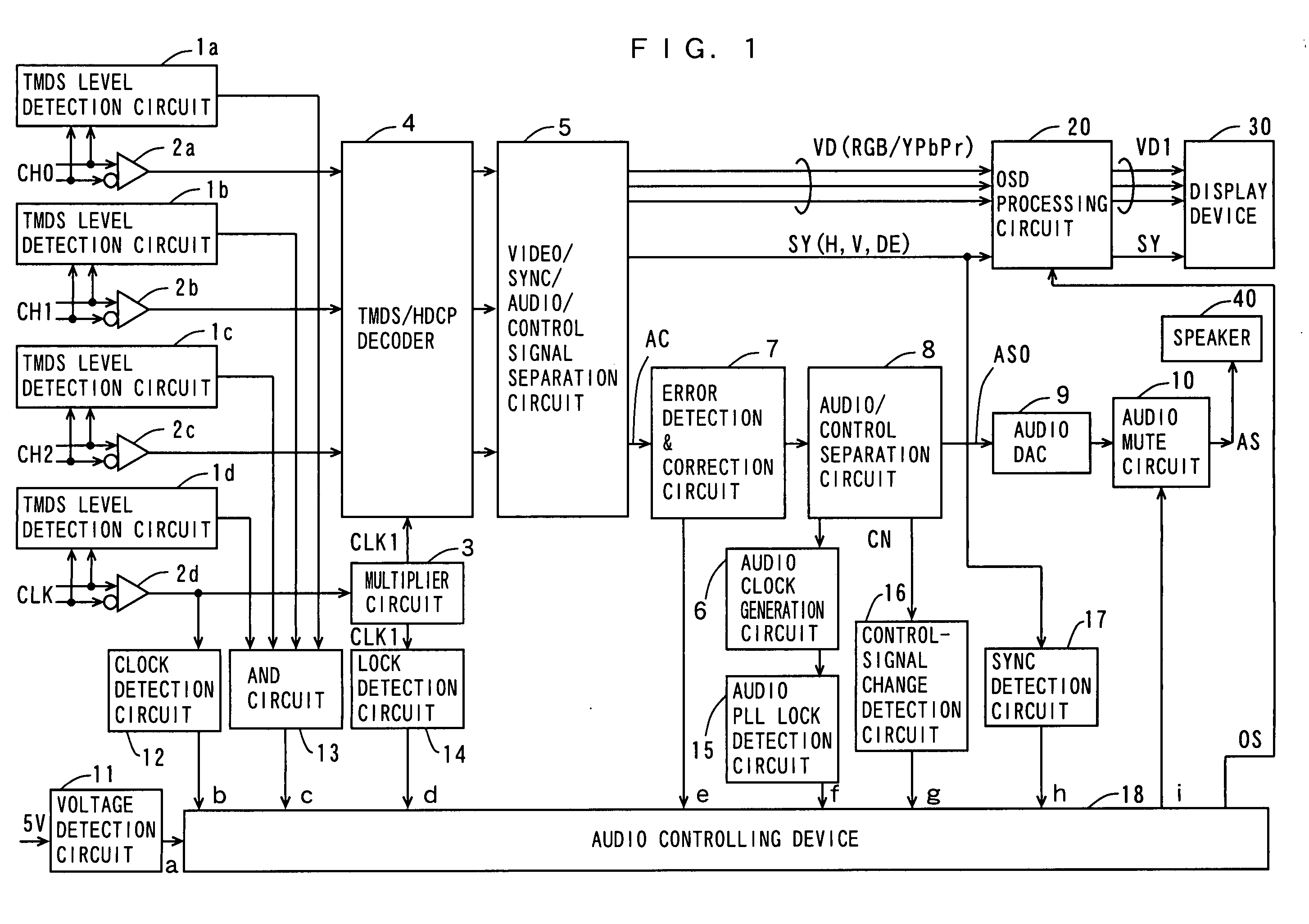
[0061]FIG. 1 is a block diagram that shows the structure of a high-speed digital video / audio interface receiver according to one embodiment of the invention.

[0062] In FIG. 1, the high-speed digital video / audio interface receiver (which will be referred to as the digital interface receiver) comprises: a plurality of TMDS level detection circuits 1a, 1b, 1c, 1d; a plurality of differential buffers 2a, 2b, 2c, 2d; a multiplier circuit 3; a TMDS / HDCP (Hi-Bandwidth Digital Content Protection) decoder 4; a video / sync / audio / control signal separation circuit (which will be referred to as a separation circuit) 5; an audio clock generation circuit 6; an error detection / correction circuit 7; an audio / control separation circuit (which will be referred to as a separation circuit) 8; an audio DAC (Digital-to-Analog Converter) 9; and an audio mute circuit 10. This digital interface receiver comprises: a voltage detection circuit 11; a clock detection circuit 12; an AND circuit 13; a lock detectio...


PUM


Abstract

An audio controlling device generates an audio mute signal based on the level of a power-supply voltage supplied from the source equipment, whether a clock signal has been input or not, whether a digital signal has been input or not, whether a multiplier circuit is being locked or not, an error rate, whether an audio clock detection circuit is being locked or not, the presence or absence of a change in a control signal, and whether a synchronization detection circuit is stable or not. The audio controlling device applies the audio mute signal to an audio mute circuit, while applying an OSD control signal to an OSD processing circuit. The audio mute circuit is placed in a mute state or unmute state based on the audio mute signal. The OSD processing circuit provides the on-screen display of a message based on the OSD control signal.

Description

TECHNICAL FIELD [0001] The present invention relates to a digital interface receiver in accordance with a transmission standard that provides for transmission of a digital signal containing an audio signal. BACKGROUND ART [0002] In recent years, the development of a variety of electronic equipment in accordance with high-speed digital interface standards, such as the HDMI (High Definition Multimedia Interface) standard or DVI (Digital Visual Interface) standard, is in progress. The HDMI standard, in particular, defines the transmission of an audio signal and a control signal during the video blanking interval. These high-speed digital interface standards adopt the so-called TMDS (Transmission Minimized Differential Signaling) serial transmission system. [0003]FIG. 6 is a diagram that shows an example of a conventional DVI compliant signal transmission system (DDWG, “Digital Visual Interface,” Revision 1.0, Apr. 2, 1999, Internet <URL: http: / / www.ddwg.org / >). [0004] The signal ...

Claims


Application Information

Patent Timeline
Patent Type & Authority Applications(United States)
IPC IPC(8): G06F13/24H04N5/44H04N5/60H04N7/173
CPCG09G5/006G09G2370/045G09G2370/12H04N5/445H04N5/60H04N21/4882H04N17/004H04N21/43635H04N21/4396H04N21/44231H04N11/042
Inventor NIO, YUTAKANAGATA, KOUICHIROTANAKA, KOICHI
Owner PANASONIC CORP
Learn More