Buffer for testing a memory module and method thereof

a memory module and buffer technology, applied in the field of buffers for testing memory modules and methods thereof, can solve problems such as performance degradation, signal integrity, undesired noise, etc., and achieve the effect of improving the stability and reliability of the memory system

Inactive Publication Date: 2006-05-04
SAMSUNG ELECTRONICS CO LTD
View PDF6 Cites 7 Cited by
  • Summary
  • Abstract
  • Description
  • Claims
  • Application Information

AI Technical Summary

Problems solved by technology

Signal integrity design criteria may include performance degradation due to a distortion of a signal waveform.
Crosstalk may refer to a phenomenon where a signal transmitted through one of a plurality of channels may cause undesired noise in a neighboring or adjacent channel due to a cross-coupling capacitance.
Signal integrity may also affect memory system operation.
However, adjusting the test program stored in the BIST circuit may be problematic in conventional memory systems.
Typically, the pseudo random bit data may not be capable of external control and may rather be based only on portions embedded on the memory module.
Further, conventional BIST circuits may have address limitations such that not all addresses of the tested memory modules may be tested.
However, if a BIST is used to perform the signal integrity test, the tested memory modules may be limited to a fixed test pattern (e.g., as stored in the embedded memory) which may make the test less reliable for predicting the performance of the tested memory modules.
Further, if the transparent mode test is performed to reduce the afore-mentioned problem of BIST circuits, the signals received from the test equipment may be input directly to memory, which may potentially cause a difference between a pin number in the tested memory module and a pin number designated for testing the memory module, which may thereby reduce a reliability of the transparent mode test.

Method used


Image

  • Buffer for testing a memory module and method thereof
  • Buffer for testing a memory module and method thereof
  • Buffer for testing a memory module and method thereof

Examples


Embodiment Construction

[0025] Hereinafter, example embodiments of the present invention will be explained in detail with reference to the accompanying drawings.

[0026] It will be understood that, although the terms first, second, etc. may be used herein to describe various elements, these elements should not be limited by these terms. These terms are only used to distinguish one element from another. For example, a first element could be termed a second-element, and, similarly, a second element could be termed a first element, without departing from the scope of the present invention. As used herein, the term “and / or” includes any and all combinations of one or more of the associated listed items.

[0027] It will be understood that when an element is referred to as being “connected” or “coupled” to another element, it can be directly connected or coupled to the other element or intervening elements may be present. In contrast, when an element is referred to as being “directly connected” or “directly couple...


PUM


Abstract

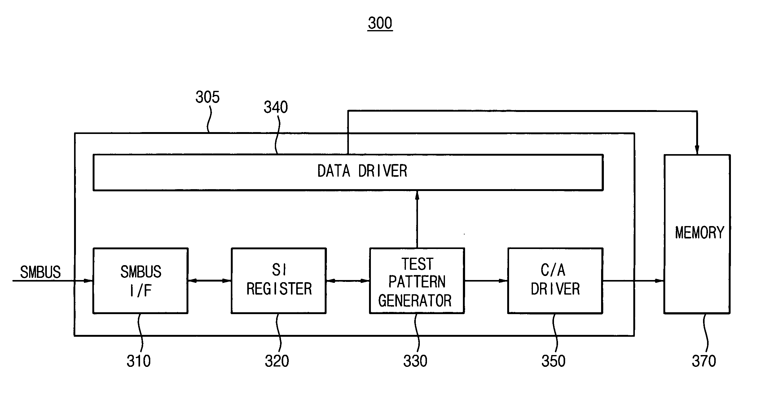
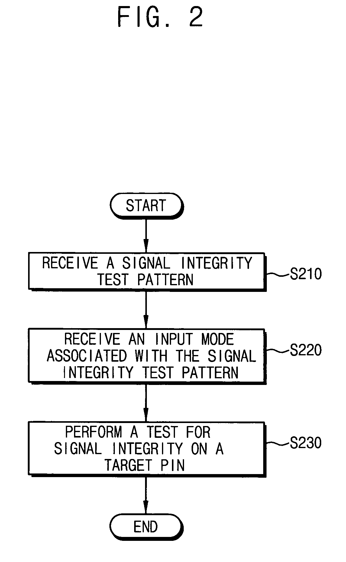
In a method, a test pattern and an associated input mode may be received where the input mode may indicate a manner of applying the test pattern. An output test pattern is applied to at least one of a plurality of memory interface pins in accordance with the input mode. In a buffer, a test register may be configured to receive and store a test pattern and an associated input mode where the input mode may indicate a manner of applying the test pattern. The buffer may further include a test pattern generator configured to repeatedly generate an output test pattern based on the associated input mode.

Description

PRIORITY STATEMENT [0001] This application claims priority under 35 USC §119 to Korean Patent Application No. 2004-89218, filed on Nov. 4, 2004, the contents of which are herein incorporated by reference in their entirety for all purposes. BACKGROUND OF THE INVENTION [0002] 1. Field of the Invention [0003] Example embodiments of the present invention relate generally to a buffer of a memory module and method thereof, and more particular to a buffer for testing a memory module and method thereof. [0004] 1. Description of the Related Art [0005] A memory module having a plurality of chips mounted on a printed circuit board (PCB) may be classified as a single in-line memory module (SIMM) or a dual in-line memory module (DIMM). A SIMM may be a memory module having memory chips mounted on a single side of a PCB and a DIMM may be a memory module having memory chips mounted on both sides of the PCB. [0006] The DIMM may be further classified as a registered DIMM (RDIMM) or a fully buffered D...

Claims


Application Information

Patent Timeline
Patent Type & Authority Applications(United States)
IPC IPC(8): G11C29/00
CPCG11C5/04G11C29/1201G11C29/48G11C2029/3602G11C29/00G11C7/10
Inventor LEE, KEE-HOONSHIN, SEUNG-MAN
Owner SAMSUNG ELECTRONICS CO LTD
Why Eureka
Try Eureka