Riving knife assembly

a technology of riving knives and assembly parts, which is applied in the field of riving knives, can solve the problems of reducing the variety of cuts that can be performed by the sawing device, affecting the production of riving knives, and affecting the quality of riving knives, so as to reduce the time spent establishing the blade of the riving knife, increase the production, and reduce the time spent establishing the blad

Inactive Publication Date: 2006-05-11
BLACK & DECKER INC
View PDF4 Cites 45 Cited by
  • Summary
  • Abstract
  • Description
  • Claims
  • Application Information

AI Technical Summary

Benefits of technology

[0013] Accordingly, it is an object of the present invention to provide a riving knife assembly enabled with a quick change capability. The quick change capability promoting a more efficient riving knife capability. For instance, a user of the quick change riving knife may be enabled to reduce the time spent establishing a riving knife blade upon a saw assembly, thereby, promoting an increase in saw assembly up time which may further promote an increase in production by the saw assembly. Another object of the quick change riving knife may be assisting in promoting an easier to implement riving knife which may further promote an increase in the safety of operation of the saw assembly.
[0014] It is a further object of the present invention to provide an adjustment assembly which may enable a user to selectively determine the position of a riving knife blade with respect to the saw assembly. It is generally accepted that the riving knife blade is established in a position behind the saw blade or opposite the side of the saw blade which establishes a cutting interface with a work piece. However, the present invention enables the user to adjust the vertical orientation and horizontal orientation of the riving knife blade with respect to the position behind the saw blade. Adjustment of the horizontal orientation enables the user may move the riving knife blade closer to or further away from the saw blade. The vertical adjustment capability enables the movement of the riving knife blade up or down relative to the saw blade. It is understood that the movement of the riving knife blade correlates to a change in the position of the riving knife blade relative to a work surface of the saw assembly.
[0015] It is a still further object of the present invention to provide a biasing assembly which operates upon a riving knife of a saw assembly. The biasing assembly for enabling the maintenance of the riving knife in the kerf of a work piece being cut by a saw blade of the saw assembly. The biasing assembly may be enabled to provide a constant force. Alternatively, the biasing assembly may be enabled with a user selectable capability which allows the user to determine the position of the riving knife provided by the biasing assembly.
[0016] The present invention further contemplates the riving knife of the present invention may be variously configured to include a variety of additional features. Such features including a blade guard which may be integral with the riving knife. In alternative embodiments, the blade guard may be coupled in a manner which allows the removal of the blade guard from the riving knife. Additionally, the riving knife may be configured with a spring tab mechanism or a wedge flange. These features may provide assistance in preventing the “kick-up” of a work piece as it is being cut by the saw blade. Another feature may include establishing the riving knife as a friction riving knife. The friction riving knife providing the blade with a further alternative method of assisting in the prevention of “kick-up” of a work piece.

Problems solved by technology

However, in many typical applications a riving knife may be attached to a table saw in such a way as to make changing the riving knife difficult.
This limited application severely limits the variety of cuts capable of being performed by the saw device and may force operators of saw devices to have to remove the riving knife when it is incapable of providing the needed orientation.
This results in decreased production and increased costs as operators are forced to spend valuable time removing and installing the riving knife for separate cuts.
But in many instances, the conventional use of a screwdriver, wrench, or other suitable device to tighten or loosen the fasteners securing a riving knife may not be desirable.
The riving knife may be recessed within a casing or surrounded by an additional assembly, making it difficult if not impossible to access the fasteners securing the riving knife with a screwdriver, wrench, or other suitable device of sufficient size to provide adequate mechanical advantage.
Another problem arises when a riving knife must be secured or removed at a remote location.
Further, securing or removing a riving knife with a screwdriver, wrench, or some other suitable device may be dangerous.
The most effective location for such a handhold is in the plane of the fastener, which typically corresponds to the plane of the saw blade; thus, a poorly chosen handhold could prove disastrous.
Unfortunately, with the typical riving knife assembly employed today, operators are forced to expend time and labor making the required removals and installations as mentioned above.
This results in increased production costs and decreased productivity.
Further, the difficulty of installing and removing these riving knifes may result in harm to the operator and the machinery.
While some riving knife assemblies have moved very small distances away from the blade they still present a risk to the operator in that to interact with the riving knife the operator's body parts are often within the area of operation of the saw blade.
Unfortunately, these blade guards are often very large and cumbersome to work with.
Further, they may serve to impede an operator's view of the work area of the saw blade.
Another frequently encountered problem when using saw devices to operate upon a work piece is “kick up”.
Kick up results in the board moving out of the plane of a work area which can lead to damage to the rest of the work piece as it is being fed through the saw blade and even harm to the operator.
It is commonplace for saw devices to employ separate machinery, such as rollers, to prevent “kick up”; however, this machinery typically requires a significant investment of money for acquisition and may tally significant maintenance costs for operation.

Method used


Image

  • Riving knife assembly
  • Riving knife assembly
  • Riving knife assembly

Examples


Embodiment Construction

[0035] Reference will now be made in detail to the presently preferred embodiments of the invention, examples of which are illustrated in the accompanying drawings.

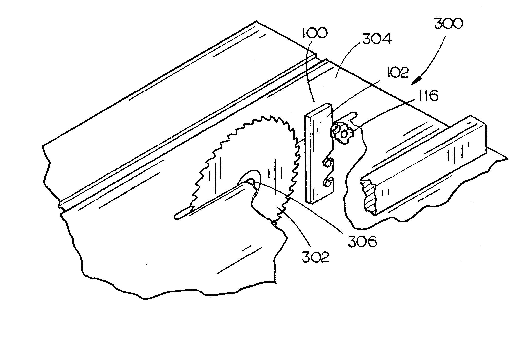
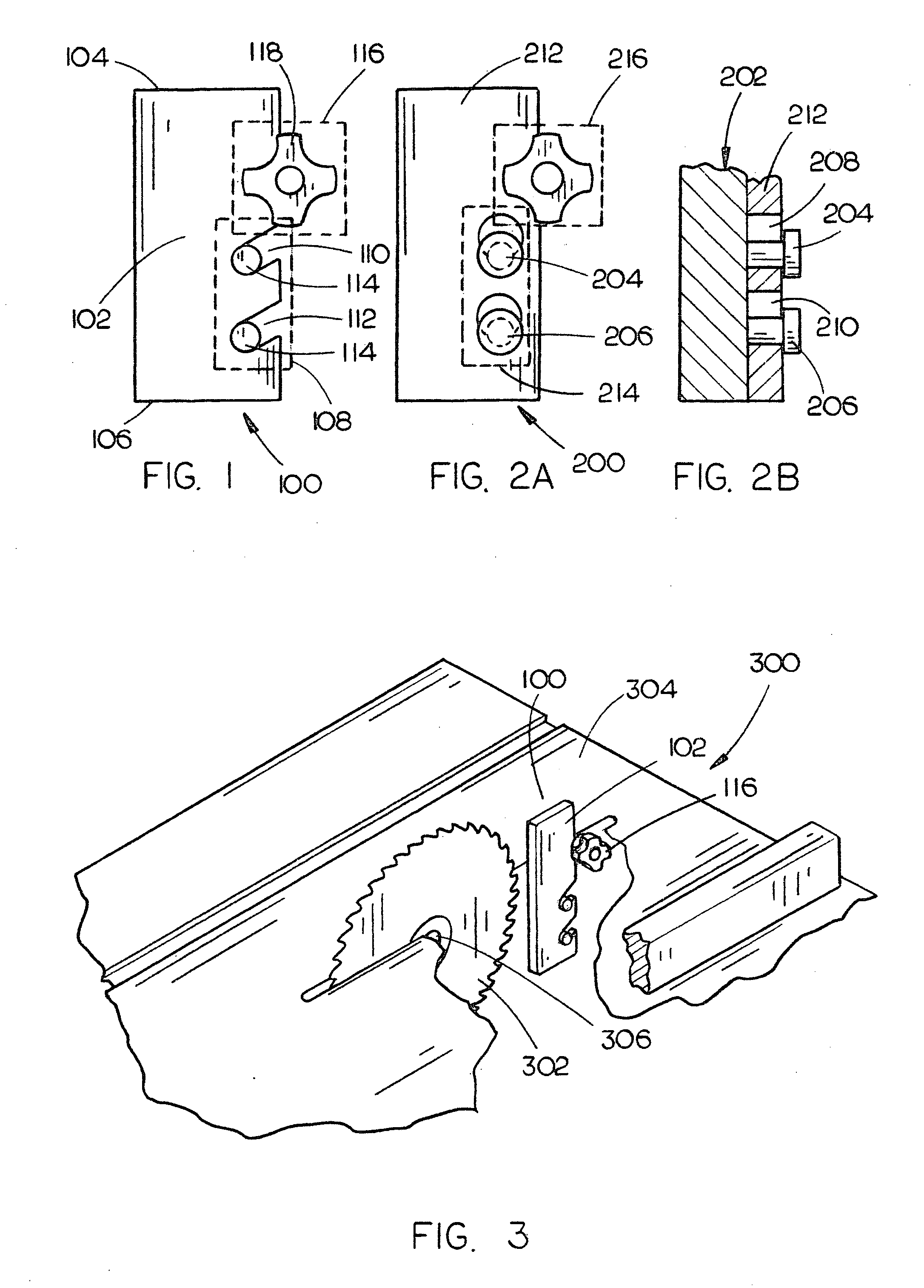
[0036] Referring generally now to FIGS. 1 through 15, exemplary embodiments of the present invention are shown. It is understood that riving knife assemblies are typically employed with saw assemblies, such as table saws. Many of these table saw assemblies include arbor assemblies which operationally couple a motor with a circular saw blade 302, the motor imparting an angular momentum to the circular saw blade 302 for the performance of a cutting functionality by the circular saw blade 302 upon a work piece. A plurality of teeth of the circular saw blade 302 engage with the work piece establishing a cutting interface at a first “leading” edge of the circular saw blade 302. The cutting interface of the saw blade 302 establishes a kerf in the work piece, that kerf enabling the work piece to continue past the sides of the s...


PUM

PropertyMeasurementUnit
frictionaaaaaaaaaa
forceaaaaaaaaaa
heightaaaaaaaaaa

Abstract

The present invention provides a riving knife assembly for use with a saw assembly, such as a table saw. The riving knife assembly is enabled with a riving knife blade having a first end for extending above a planar work surface established by the saw assembly and a second end for connecting the riving knife with the saw assembly. The second end of the riving knife blade includes a riving engagement mechanism which enables the riving knife blade to connect with a saw coupling mechanism in a manner which may promote the riving knife blade to be more quickly and easily inserted into and / or removed from an operational stance with the saw assembly.

Description

CROSS REFERENCE TO RELATED APPLICATION [0001] The present invention claims priority under 35 U.S.C. §119(e) to the U.S. Provisional Application Ser. No. 60 / 455,074, filed on Mar. 14, 2003, which is herein incorporated by reference in its entirety.FIELD OF THE INVENTION [0002] The present invention relates generally to riving knives, and more specifically to riving knife assemblies for use with a saw assembly, such as a table saw, a circular saw, a band saw, a hand saw, and the like. BACKGROUND OF THE INVENTION [0003] Riving knives are used with a variety of saw assemblies and serve a number of purposes. One purpose a riving knife may serve is to stabilize a work piece as it is being cut, the knife being engaged in the slot, groove, notch, and the like (kerf) created by a saw blade as the work piece is fed in the cutting direction. Another purpose a riving knife may serve is to keep the kerf open as the work piece is fed into or across the saw blade. This action may prevent binding o...

Claims


Application Information

Patent Timeline
Patent Type & Authority Applications(United States)
IPC IPC(8): B23D45/06
CPCB27G19/08Y10T83/2077Y10T83/773
Inventor GARCIA, JAIME E.CARROLL, CRAIG A.DEKEYSER, KATHYROS, MATWESTON, JEFFREY D.
Owner BLACK & DECKER INC
Why Eureka
Try Eureka