Article comprising a composite cover

a composite cover and cover technology, applied in the field of canistered systems, can solve the problems of not including impact-resistant foam, but including rubber layers, and not meeting the requirements of hail impa

Inactive Publication Date: 2006-05-11
LOCKHEED MARTIN CORP
View PDF8 Cites 28 Cited by
  • Summary
  • Abstract
  • Description
  • Claims
  • Application Information

AI Technical Summary

Problems solved by technology

A previous cover design that did not include the impact-resistant foam,

Method used


Image

  • Article comprising a composite cover
  • Article comprising a composite cover
  • Article comprising a composite cover

Examples


Embodiment Construction

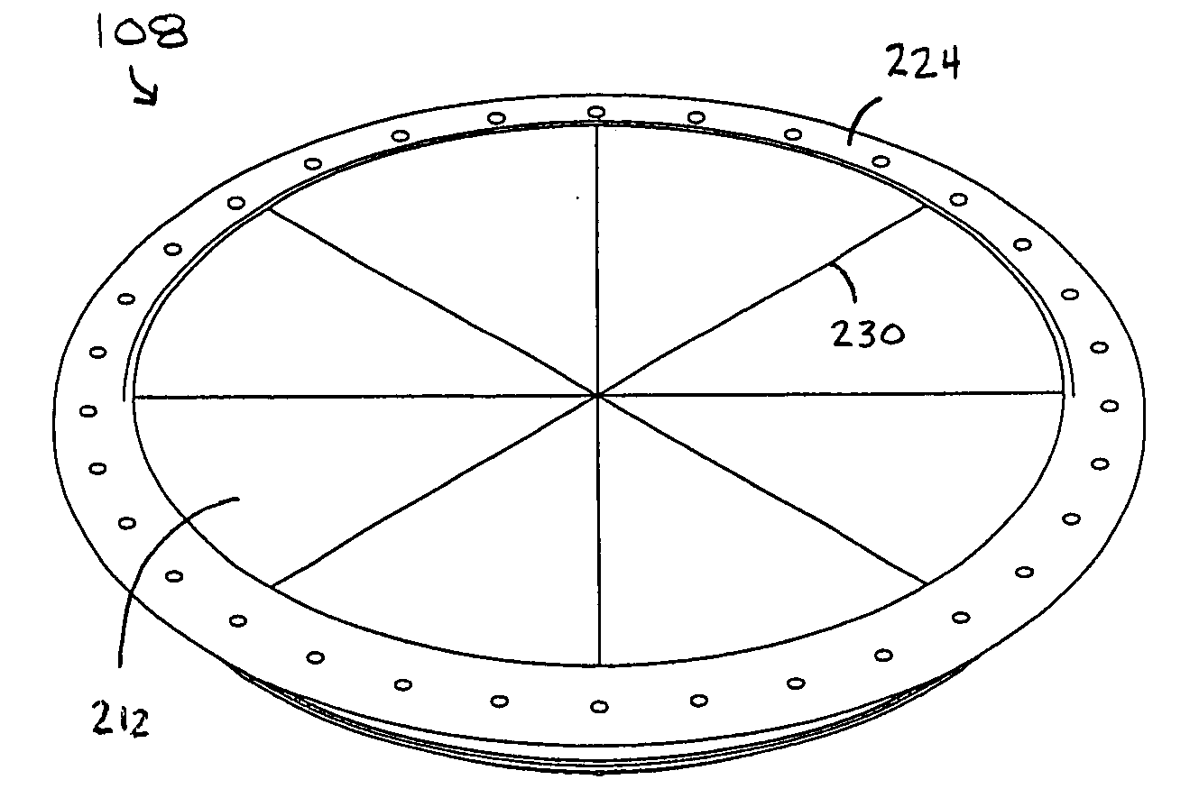
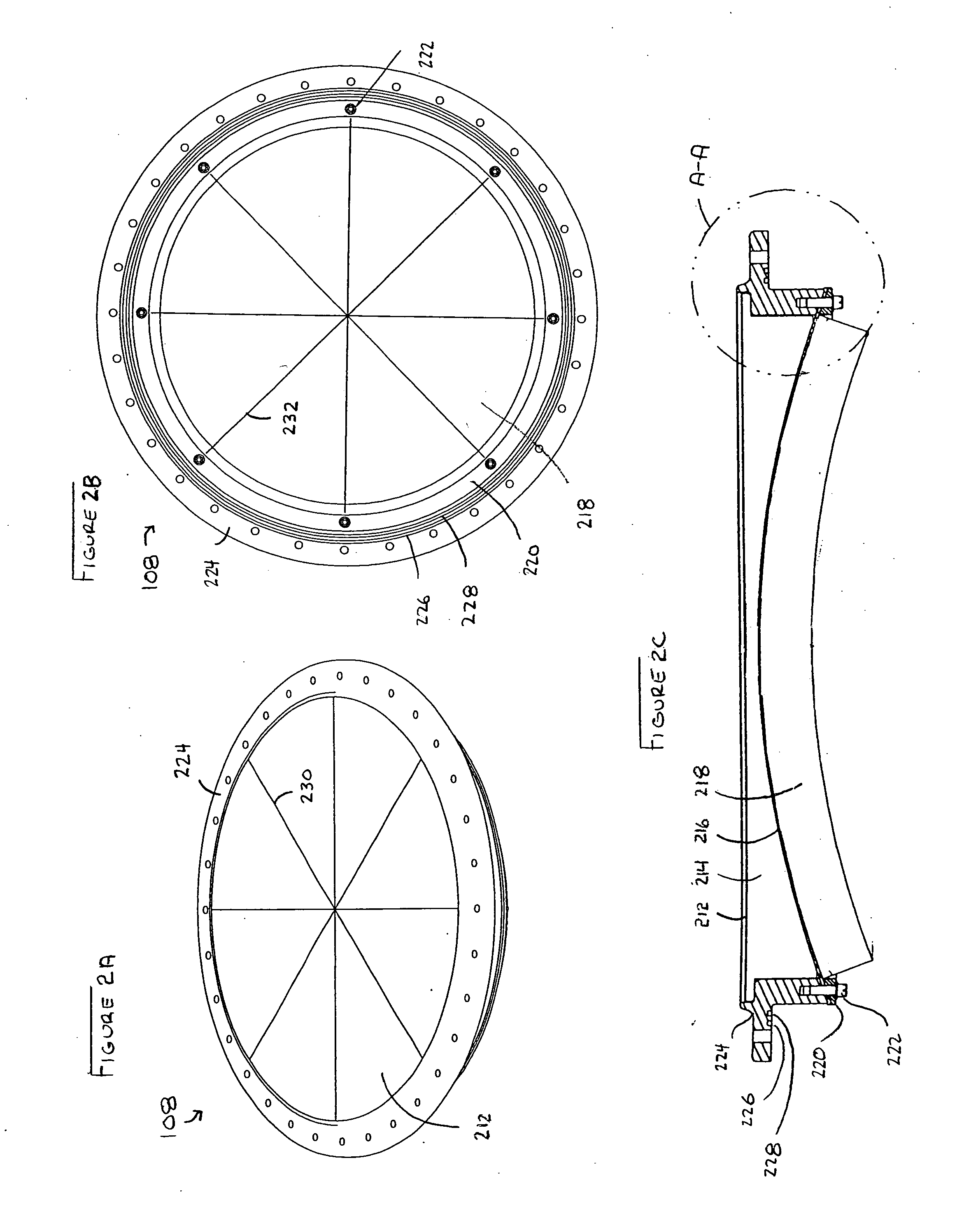
[0040] The illustrative embodiment of the present invention is a munitions canister with a cover that incorporates multiple layers of material. This multi-layer cover is useful in a variety of applications as well. For example, among other uses, the multi-layer cover is finds application as a missile-launcher opening cover, a cover for a pressurized storage vessel, an armament shipping-container cover, a transportation-container cover, and a hatch opening cover.

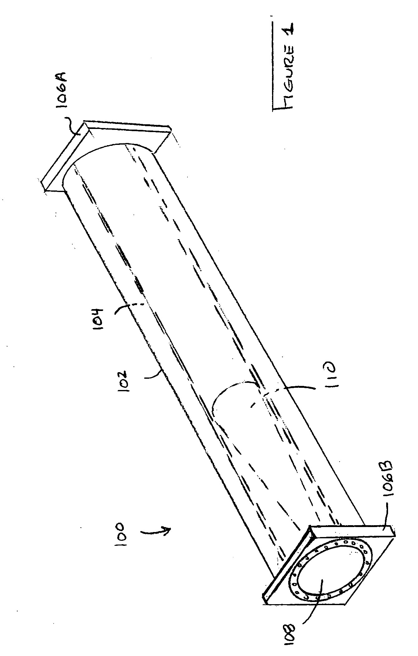
[0041]FIG. 1 depicts munitions canister 100. The munitions canister includes structural shell 102, internals 104, end frames 106A and 106B and multi-layer cover 108.

[0042] Shell 102 is typically formed of a filament wound material, such as graphite / epoxy, etc. In some embodiments, shell 102 has a layer of foam insulation for thermal protection and a fiberglass outer wrap to increase resistance to damage.

[0043] Munitions canister 100 usually includes a variety of internals, indicated generally at 104. The internals include,...


PUM


Abstract

The illustrative embodiment of the invention is a munitions canister having a cover that is impervious to a variety of environmental stresses. In the illustrative embodiment, the cover includes a layer of rubber, which overlies a layer of sectioned, impact-resistant foam, which overlies a dome-shaped, structural member, which overlies a layer of acoustical dampening foam.

Description

FIELD OF THE INVENTION [0001] The present invention relates generally to canistered systems and, more particularly, to covers for canistered systems. BACKGROUND OF THE INVENTION [0002] Munitions, such as missiles and rockets, are often launched from canisters. The canisters are typically round or square tubes that contain a munition, munition-launch hardware such as rails and / or sabots, and electronics for initiating launch. In addition to functioning as a launch system, the canisters provide environmental protection for the munition, simplify munition-handling issues, and provide an efficient and long-term munition-storage solution. [0003] In order to provide full environmental protection for the munition and other components within the canister, the canister must be sealed. This is typically done using a cap or cover. The cover is ideally able to protect or isolate the munition from a variety of environmental factors, such as variations in humidity, temperature extremes, debris im...

Claims


Application Information

Patent Timeline
IPC IPC(8): F41F3/04
CPCF41F3/077Y10T428/24479Y10T428/24628Y10T428/24496
Inventor WILLIAMS, ROBERT B.WAICUKAUSKI, JAMES A.
Owner LOCKHEED MARTIN CORP
Why Eureka
Try Eureka