Input device

a technology of input device and input jack, which is applied in the field of input device, can solve the problems of large power requirement, inability to offer a practical solution method, and operator cannot securely feel vibration, and achieve the effect of large amplitude vibration

Inactive Publication Date: 2006-05-11
ALPS ALPINE CO LTD
View PDF6 Cites 50 Cited by
  • Summary
  • Abstract
  • Description
  • Claims
  • Application Information

AI Technical Summary

Benefits of technology

[0018] The present invention has been devised in order to solve the problems of the related arts, and it is an object of the invention to provide an inpu

Problems solved by technology

Therefore, there is a problem in that the operator cannot securely feel the vibrations as a response to an input operation.
That is, the vibrating element 205 must be a large-sized in order to generate large vibrations, or large power is required since the vibrations cannot be

Method used


Image

  • Input device
  • Input device
  • Input device

Examples


Embodiment Construction

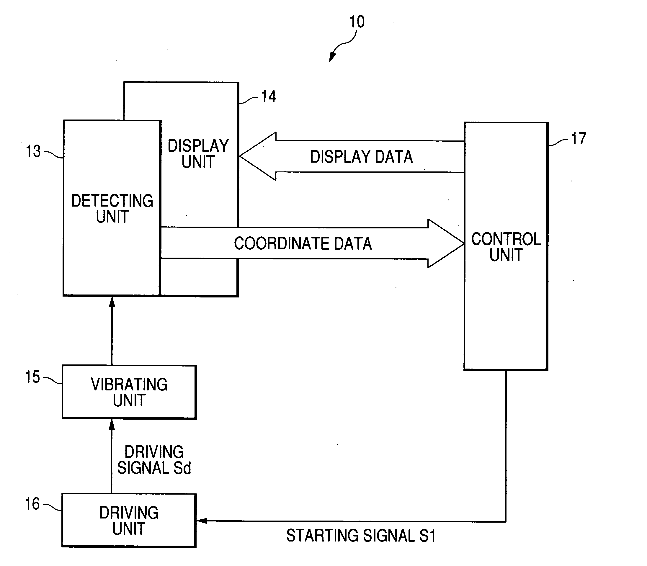
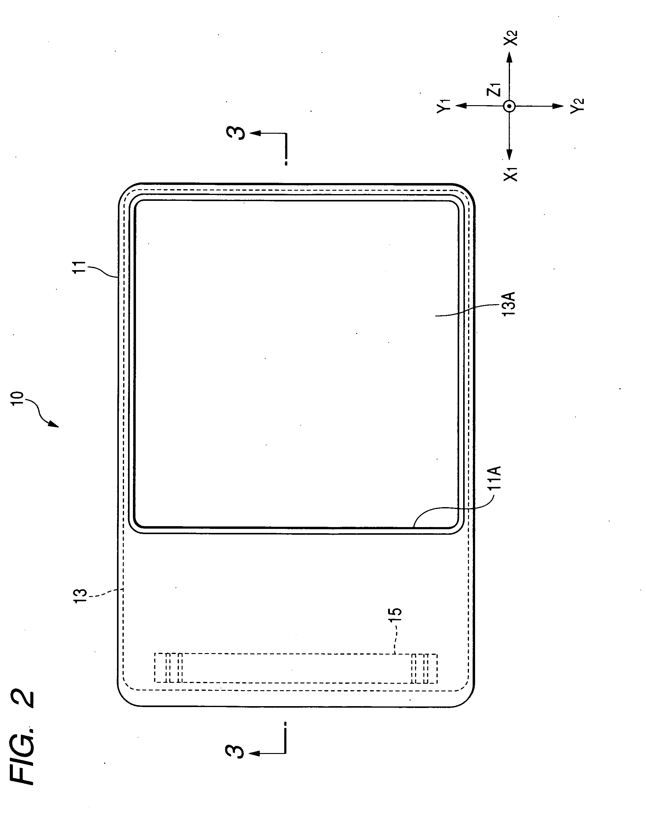
[0056]FIG. 1 is a block diagram showing the composition of a first embodiment of an input device according to the present invention, FIG. 2 is a plane view of the input device of the first embodiment seen from a panel, FIG. 3 is an enlarged cross-sectional view taken along line 3-3 in FIG. 2, FIG. 4 is an explanatory view showing the vibrations of the surface panel of the input device of the first embodiment, and FIG. 5 is an explanatory view showing the relationship between the length L1 to an exciting unit-fixed position and the supporting length L by the types of vibration.

[0057] An input device 10 will be described below by extracting a touch panel used for, for example, an automatic telling machine (ATM), an automatic ticketing machine or various portable input devices.

[0058] As shown in FIG. 1, the input device 10 includes a detecting unit 13, a display unit 14, an exciting (vibrating) unit 15, a driving unit 16, a control unit 17 or the like.

[0059] As shown in FIG. 2, the ...


PUM


Abstract

An input device is presented. The input devices contains a chassis having an opening. A detecting unit has a surface panel exposed through the opening and detects a pressing operation when the surface panel is pressed. An exciting unit vibrates the surface pane. A driving unit generates driving signals driving the exciting unit at predetermined frequencies. A control unit supplies starting signals starting the driving unit on the basis of an output from the detecting unit. The detecting unit is supported by two supporting portions provided at edge portions of the opening and has a free-end portion at the outside of one of the supporting portions and the exciting unit provided at the free-end portion.

Description

BACKGROUND OF THE INVENTION [0001] 1. Field of the Invention [0002] The present invention relates to an input device that generates vibrations as a response to an input operation on a touch panel, and in particular, to an input device that can efficiently generate vibrations and supply large vibrations throughout the touch panel as an input response. [0003] 2. Description of the Related Art [0004] Hereinafter, description of related arts will be illustrated below. JP-A-11-85400 discloses a display device in the related art, on which an input operation can be performed. [0005]FIG. 10 is an exploded perspective view showing the display device. When a pen 200 touches a display panel 201, position-detecting data representing the positions of the pen 200 are outputted to a control circuit 203 from a position sensor sheet 202. [0006] The control circuit 203 verifies the position-detecting data and the position data of specific images (object) displayed on the display panel 201 and determi...

Claims


Application Information

Patent Timeline
IPC IPC(8): G09G5/00
CPCG06F3/016
Inventor TABATA, MASASHI
Owner ALPS ALPINE CO LTD
Why Eureka
Try Eureka