Gas detection method and gas detector device

a gas detection and gas detector technology, applied in radiation pyrometry, instruments, material analysis, etc., can solve the problems of low light efficiency, high power consumption of thermal light sources, and low light efficiency of non-diffractive ir gas detectors

Active Publication Date: 2006-05-11
AXETRIS AG
View PDF13 Cites 16 Cited by
  • Summary
  • Abstract
  • Description
  • Claims
  • Application Information

AI Technical Summary

Problems solved by technology

Such non-diffractive IR (NDIR) gas detectors suffer from two drawbacks.
Firstly, thermal light sources have a high power consumption and a low light efficiency which makes battery-driven operation difficult and implies cooling issues.
Secondly, the center wavelength of interference line filters is dependent on the temperature so that for different ambient temperatures, the detection operates at different positions of the gas absorption peak which in turn makes calibration difficult.
Thus, the generation and the detection of a reference beam complicate the device and increase its production cost.
The method disclosed in U.S. Pat. No. 6,356,350 B1 is not appropriate for providing a gas detector device with low fabrication costs for large series which allows an efficient gas concentration measuring or presence of a gas.

Method used


Image

  • Gas detection method and gas detector device
  • Gas detection method and gas detector device
  • Gas detection method and gas detector device

Examples


Embodiment Construction

[0026] With reference to FIGS. 1 to 9, the method for detecting a gas concentration according to the present invention will be described.

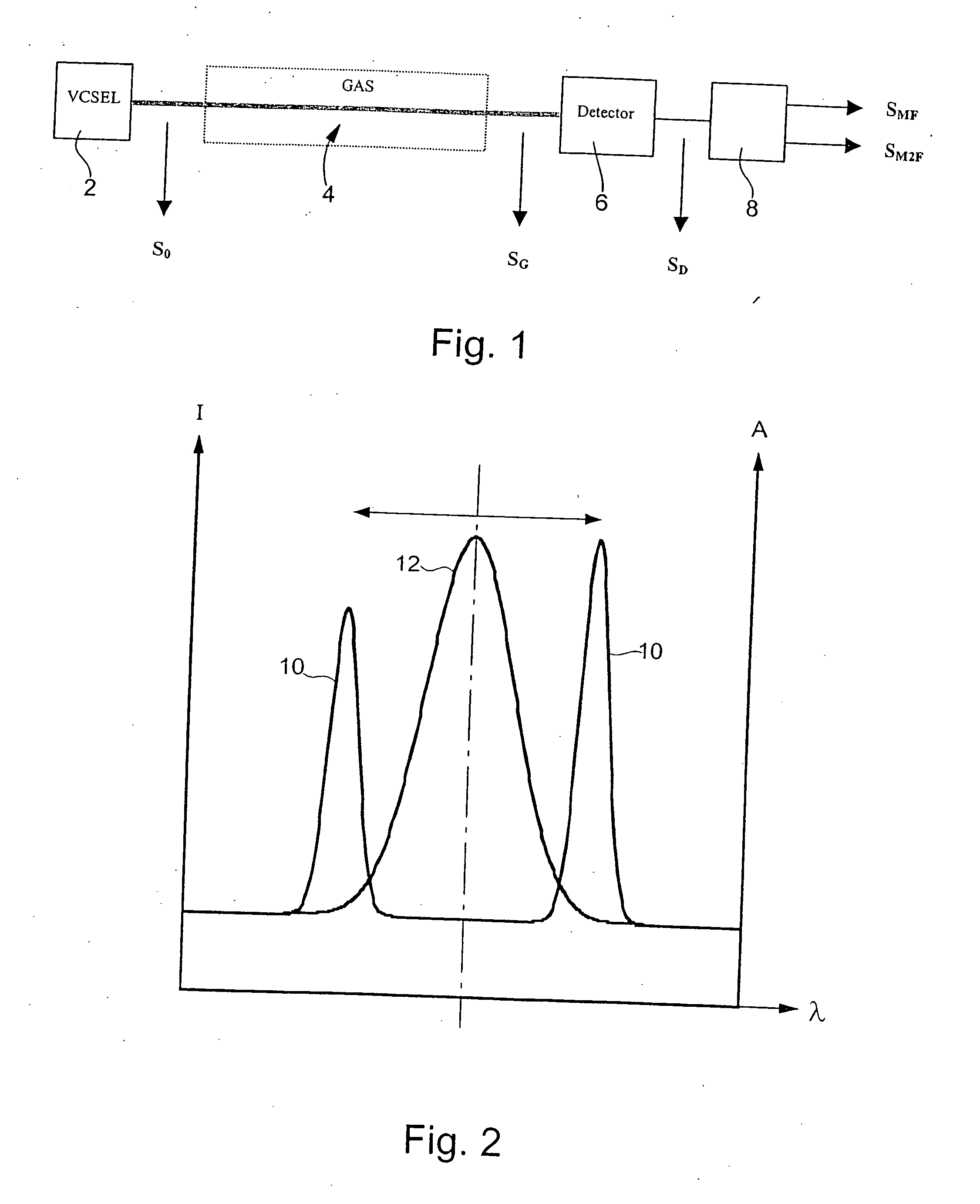
[0027] As schematically shown in FIG. 1, the gas detector device according to the invention comprises a light source formed by a VCSEL 2, a sample chamber or detection region 4 where a gas to be detected can be introduced, a light detector 6 and processing means 8 which provide two measuring signal SMF and SM2F allowing a gas concentration to be defined. The VCSEL generates an initial light beam S0 which is wavelength modulated. This light beam passes through the region 4. Due to the gas absorption, the initial light signal presents an intensity variation after having passed through the gas detection region 4 and thus the detector 6 receives a resulting light signal SG. The detector provides a corresponding detection signal SD to the processing means 8.

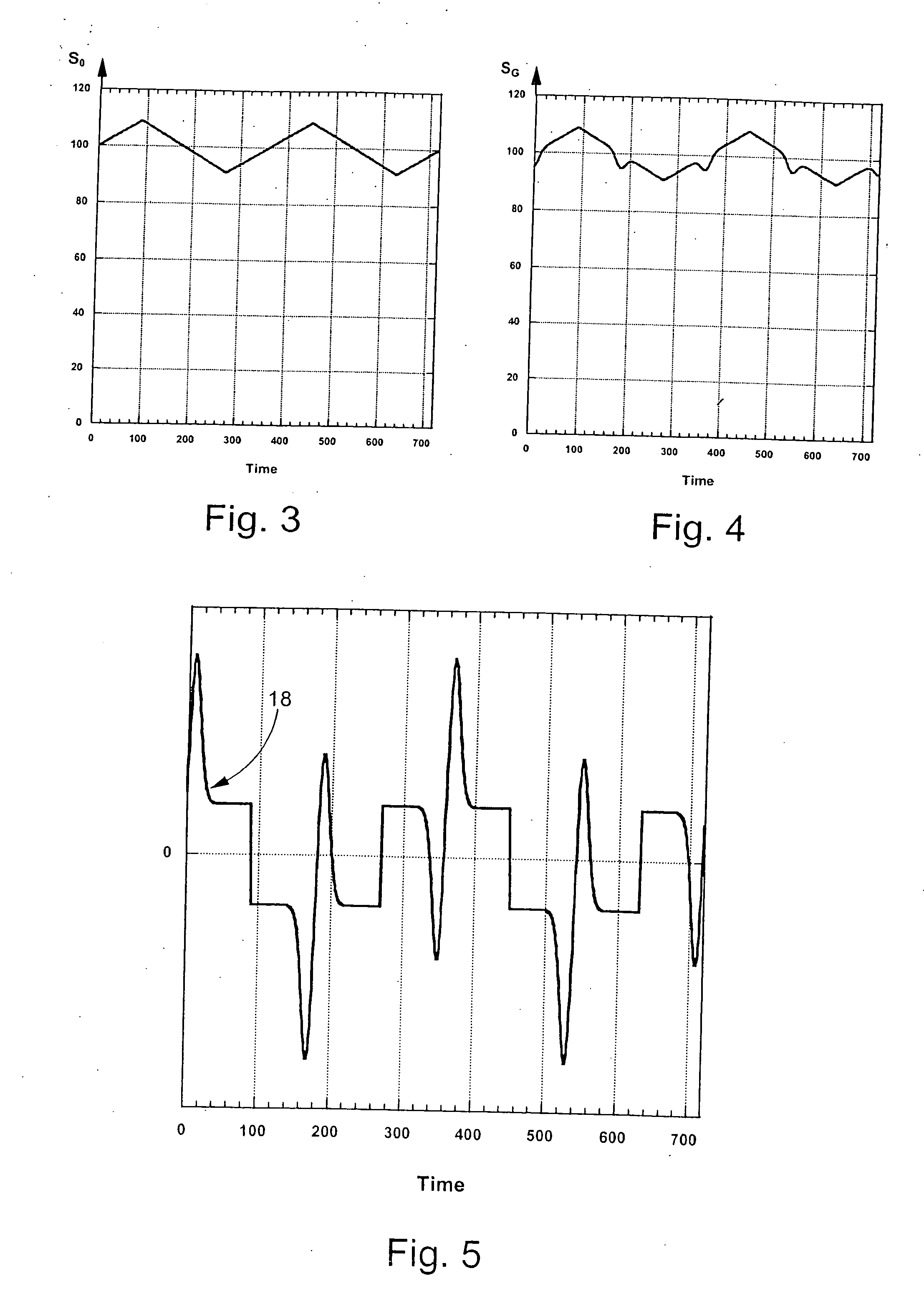
[0028] As shown in FIG. 2, the VCSEL wavelength λ (center of the light intensity peak 10) is mo...


PUM

PropertyMeasurementUnit
frequencyaaaaaaaaaa
concentrationaaaaaaaaaa
timeaaaaaaaaaa

Abstract

A gas detector device comprises at least a VCSEL source (34, 36) and at least a light sensor (54, 56) for detecting a light beam (50, 52) having passed through a sample chamber (48) containing a given gas to be detected. The sensor is a photodiode in a first embodiment and its detection signal is time derivated by an electronic derivator (64) and then provided to two lock-in amplifiers (84, 86) in order to generate a F-detection and a 2F-detection, F being the frequency of a wavelength modulation of the source, and thus to provide two corresponding measuring signals the division of which gives a precise value of the gas concentration. In a second embodiment, the source is a pyroelectric sensor which directly provides a detection signal proportional to the time derivate of the light beam incident on this sensor. In this last case, the electronic derivator is thus eliminated.

Description

BACKGROUND OF THE INVENTION [0001] The present invention concerns in particular low-cost infrared (IR) gas detection. A standard technology in this field consists in a thermal IR light source, an interference line filter, a sample chamber and an IR detector. The line filter corresponds to the characteristic absorption wavelength of the gas to be detected so that only light of this specific wavelength is incident onto the detector. If a gas to be detected is present in the sample chamber, part of the light is absorbed by the gas and the detector signal is lowered subsequently. In order to take into account the intensity variation of the light source due to aging, moisture or dirt, a part of the emitted light is directed outside the sample chamber onto a reference detector (so-called two-beam or reference-beam technique). [0002] Such non-diffractive IR (NDIR) gas detectors suffer from two drawbacks. Firstly, thermal light sources have a high power consumption and a low light efficienc...

Claims


Application Information

Patent Timeline
Patent Type & Authority Applications(United States)
IPC IPC(8): G01N21/61G01N21/31G01N21/35G01N21/39
CPCG01N21/3504G01N21/39G01N2021/3133G01N2021/3185G01N2021/399G01N2201/0691
Inventor WILLING, BERTKOHLI, MARKUSSEIFERT, ANDREAS
Owner AXETRIS AG
Why Eureka
Try Eureka