Panoramic objective and panoramic camera

a panoramic camera and objective technology, applied in the field of panoramic cameras, can solve the problem of limit to the miniaturization of such a combined mirror/lens objectiv

Inactive Publication Date: 2006-05-11
DAIMLER AG
View PDF6 Cites 0 Cited by
  • Summary
  • Abstract
  • Description
  • Claims
  • Application Information

AI Technical Summary

Benefits of technology

[0008] It is the object of the invention to specify a photographic objective with mirrors and at least one lens which can be fabricated in a simple and inexpensive manner and is well suited to miniaturization.
[0009] This object is achieved by an objective having the features of claim 1. Simplification and a miniaturization capability are achieved by the fact that a supporting body, on which the first mirror is formed, is used at the same time as barrel for holding the at least one lens. The lens is not, therefore, surrounded by a separate barrel increasing the space requirement of the objective as in conventional lens optics forming an independent constructional unit.
[0010] According to a first preferred embodiment of the invention, not only the barrel which holds the lens but also the lens itself is constructed of one piece with the support material for the mirror. This allows the supporting body of the mirror and the lens to be produced in a simple and inexpensive manner in one operating cycle, e.g. by plastic injection molding.
[0011] According to a second preferred embodiment, the lens is produced separately from the supporting body of the mirror and inserted into the barrel formed in the supporting body. This facilitates fine machining of the refractive surfaces of the lens before insertion, e.g. by polishing, applying an antireflection coating etc.

Problems solved by technology

Due to the size of this objective and the necessary distance from the mirrors predetermined by the size and focal length of the objective, there are limits to the miniaturization of such a combined mirror / lens objective.
This represents an adjustment effort.

Method used


Image

  • Panoramic objective and panoramic camera
  • Panoramic objective and panoramic camera
  • Panoramic objective and panoramic camera

Examples


Embodiment Construction

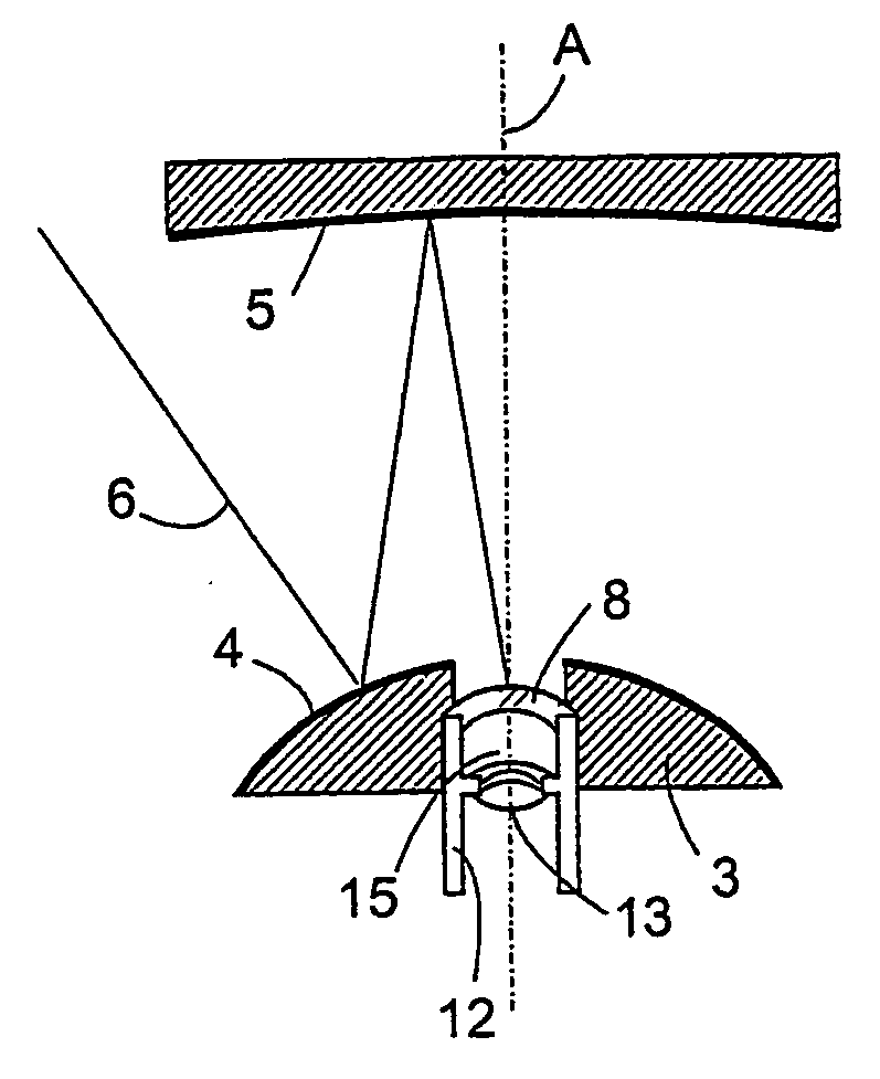
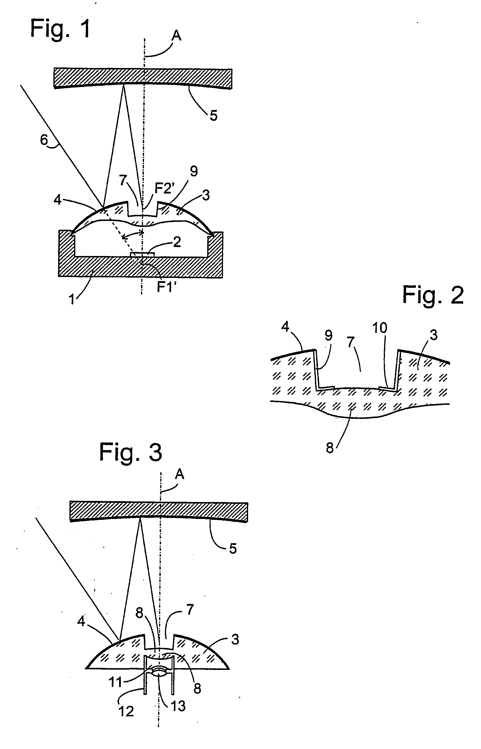
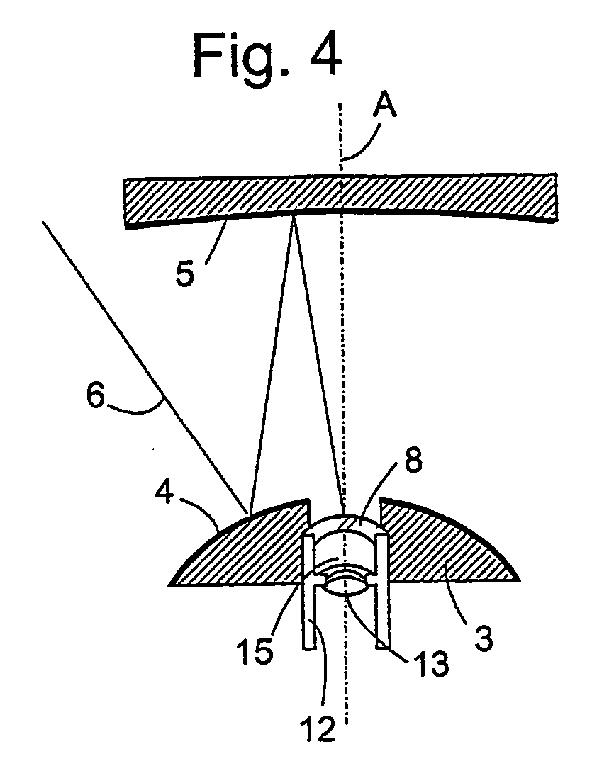
[0019]FIG. 1 shows a diagrammatic section through a camera comprising a mirror-lens objective according to a first embodiment of the invention. The camera comprises a cup-like housing 1 with a light-sensitive element such as CCD (Charge Coupled Device) 2 arranged on the optical axis A. The housing is closed at its top by a supporting body 3 of a transparent material in optical quality. The supporting body 3 has an outside surface in the form of a convex rotational hyperboloid symmetrical about the optical axis A, on which an aluminum or silver layer is vapour-deposited in order to form a first mirror 4. At a distance above the first mirror 4, a second mirror 5 is arranged which here takes the form of a concave rotational hyperboloid. Light rays 6, which are incident on the first mirror 1 at arbitrary azimuth angles and from a wide range of zenith angles θ are reflected from the first mirror 1 to the second mirror 5 and from there into a central recess 7 of the supporting body 3 in w...


PUM


Abstract

The invention relates to a photographic objective comprising a first (4) and at least one second mirror (5) and at least one lens (8). A barrel (7, 11), inside of which the lens (8) is anchored, is formed by a supporting body (3) of the first mirror (4).

Description

BACKGROUND OF THE INVENTION [0001] 1. Field of the Invention [0002] The present invention relates to an objective which uses both mirrors and lenses for image formation, and to a camera exhibiting such an objective. [0003] 2. Related Art of the Invention [0004] Non-planar imaging mirrors have long been used in photographic objectives for extremely long focal lengths, since they make it possible to make these objectives much shorter than they would be according to their focal length, thus considerably reducing the weight of such an objective in comparison with a corresponding objective in lens optics and improving its manageability. [0005] In recent years, numerous constructions of objectives having extremely wide visual angles up to a panoramic view of 360° have been proposed which use non-planar mirror surfaces as imaging elements. An overview of the constructions of such objectives and the types of mirror surfaces used in these is given in the article “Folded Catadioptric Cameras”...

Claims


Application Information

Patent Timeline
Patent Type & Authority Applications(United States)
IPC IPC(8): G02B13/06G02B17/08
CPCG02B13/06
Inventor WUERZ-WESSEL, ALEXANDER
Owner DAIMLER AG
Why Eureka
Try Eureka