Circuit connecting material, film-like circuit connecting material using the same, circuit member connecting structure, and method of producing the same

Inactive Publication Date: 2006-05-11
HITACHI CHEM CO LTD
View PDF7 Cites 41 Cited by
  • Summary
  • Abstract
  • Description
  • Claims
  • Application Information

AI Technical Summary

Benefits of technology

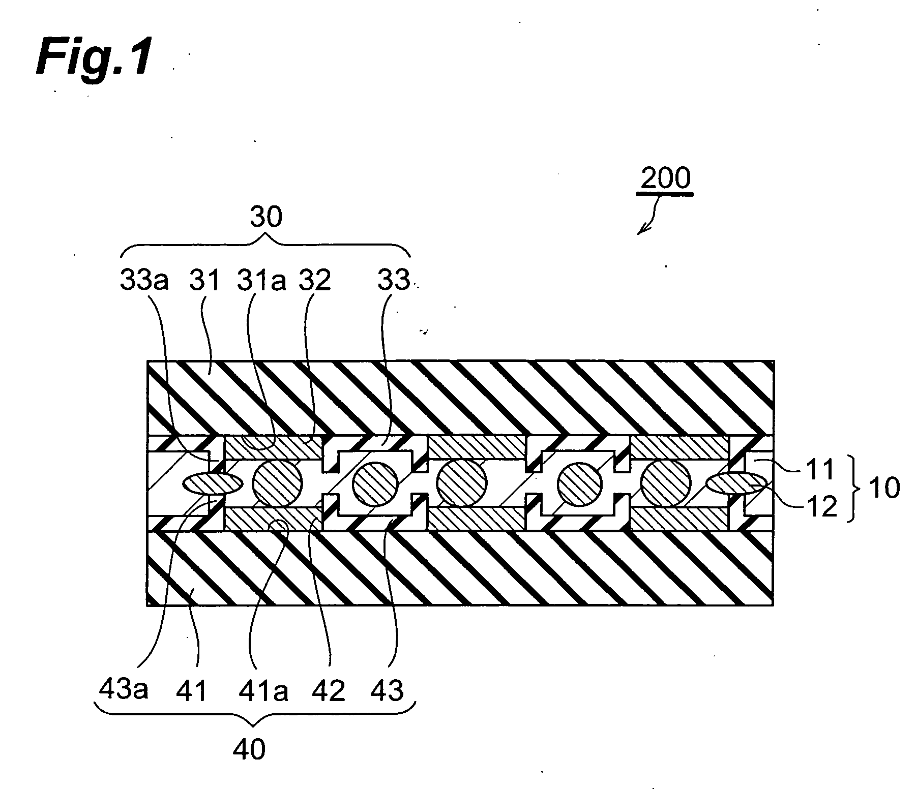
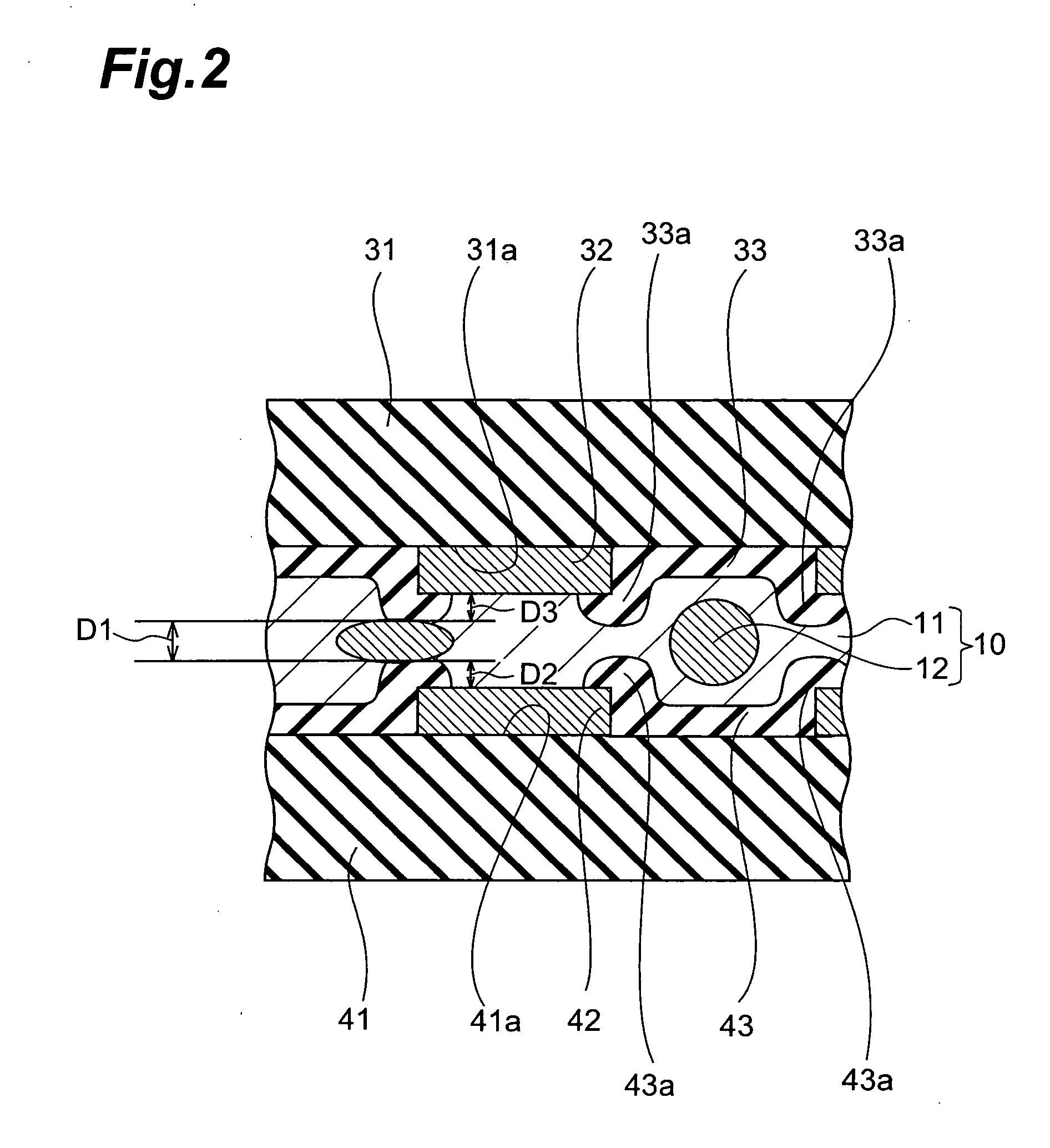
[0017] In this method for manufacturing a circuit member connecting structure, when the abovementioned circuit connecting material is interposed between the first circuit member and second circuit member and is subjected to a curing treatment by the application of heat and pressure via the first and second circuit members, the connection resistance between the facing circuit electrodes can be sufficiently reduced, and a circuit member connecting structure that is superior in terms of the long-term reliability of the electrical characteristics can be obtained.
[0018] The reason that a circuit member connecting structure in which the connection resistance between the facing circuit electrodes can be sufficiently reduced is obtained is thought to be as follows: namely, even if conductive particles become caught between the insulating layers and the facing circuit electrodes, or between insulating layers that face each other, when the circuit members are connected to each other, the conductive particles are appropriately flattened, so that the distance between the facing circuit electrodes can be sufficiently reduced. Furthermore, the reason that a circuit member connecting structure that is superior in terms

Problems solved by technology

However, the abovementioned conventional circuit member connecting structure 100 has suffered from the following problems.
Specifically, in the circuit member connecting structure 100 shown in FIG. 7, the follo

Method used


Image

  • Circuit connecting material, film-like circuit connecting material using the same, circuit member connecting structure, and method of producing the same
  • Circuit connecting material, film-like circuit connecting material using the same, circuit member connecting structure, and method of producing the same
  • Circuit connecting material, film-like circuit connecting material using the same, circuit member connecting structure, and method of producing the same

Examples


Example

Example 1

[0114] 50 g of a phenoxy resin (commercial name: PKHC, manufactured by Union Carbide K.K., average molecular weight 45,000) was dissolved in a mixed solvent of toluene / ethyl acetate (=50 / 50 in terms of weight ratio), thus producing a solution with a solid content of 40 wt %.

[0115] Next, 30 g of a phenoxy resin, 30 g of a bisphenol A type epoxy resin and 40 g of Novacure (commercial name 3941HPS, manufactured by Asahi-Ciba K.K.) used as a latent curing agent for the epoxy resin (all amounts here are given in terms of solid content weight ratio) were added to the abovementioned solution. Furthermore, 5 volume parts of conductive particles No. 1 were further added and dispersed in this solution per 100 volume parts of the bonding agent composition, thus preparing a liquid containing a circuit connecting material. Furthermore, the Novacure 3941HPS of the abovementioned latent curing agent is a master batch type curing agent in which a micro-encapsulated curing agent with a me...

Example

Example 2

[0117] The film-form circuit connecting material of Example 2 was obtained in the same manner as in Example 1, except for the fact that conductive particles 2 were used instead of the conductive particles 1 used in Example 1.

Example

Example 3

[0118] The film-form circuit connecting material of Example 3 was obtained in the same manner as in Example 1, except for the fact that conductive particles 3 were used instead of the conductive particles 1 used in Example 1.


PUM

PropertyMeasurementUnit
Temperatureaaaaaaaaaa

Abstract

The present invention is a circuit connecting material used for the mutual connection of a circuit member in which electrodes and insulating layers are formed adjacent to each other on the surface of a board, and a circuit member in which electrodes and insulating layers are formed adjacent to each other on the surface of a board, with the edge parts and of the insulating layers being formed with a greater thickness than the electrodes on the basis of the main surfaces, wherein this circuit connecting material contains a bonding agent composition and conductive particles that have a mean particle size of 1 μm or greater but less than 10 μm and a hardness of 1.961 to 6.865 GPa, and this circuit connecting material exhibits a storage elastic modulus of 0.5 to 3 GPa at 40° C. and a mean coefficient of thermal expansion of 30 to 200 ppm/° C. at from 25° C. to 100° C. when subjected to the curing treatment.

Description

TECHNICAL FIELD [0001] The present invention relates to a circuit connecting material, a film-form circuit connecting material using this circuit connecting material, a circuit member connecting structure and a method of manufacturing this circuit connecting structure. BACKGROUND ART [0002] Circuit member connecting structures used for the mutual connection of circuit members such as liquid crystal displays and TCPs (tape carrier packages), FPCs (flexible printed circuits) and TCPs, FPCs and printed wiring boards or the like have been known in the past. Circuit connecting materials in which conductive particles are dispersed in a bonding agent (e.g., anisotropic conductive bonding agents) are used for the connection of such circuit members to each other (for example, see Japanese Patent Application Laid-Open No. 59-120436, Japanese Patent Application Laid-Open No. 60-191228, Japanese Patent Application Laid-Open No. 1-251787, Japanese Patent Application Laid-Open No. 7-90237 and Jap...

Claims


Application Information

Patent Timeline
IPC IPC(8): C08K9/12C09J9/02C09J163/00H01B1/22H01L21/60H05K3/32H05K3/34
CPCC09J9/02H01L2924/0002H01B1/22H01L24/29H01L24/83H01L2224/29399H01L2224/32225H01L2224/83101H01L2924/01005H01L2924/01013H01L2924/01015H01L2924/0102H01L2924/01027H01L2924/01029H01L2924/01033H01L2924/01046H01L2924/01047H01L2924/01049H01L2924/0105H01L2924/01057H01L2924/01058H01L2924/01078H01L2924/01079H01L2924/0781H01L2924/14H01L2924/19041H01L2924/19043H05K3/323H05K3/3452H05K2203/0594H01L2924/01006H01L2924/01019H01L2924/01045H01L2924/0665H01L2924/0132H01L2224/26145H01L2224/04026H01L2224/05571H01L2224/2929H01L2224/83365H01L2224/83385H01L2224/83851Y10T156/10Y10T428/2495Y10T428/2852Y10T428/2857Y10T428/2991H01L2924/00014C09J163/00H01L2924/00H01L2224/2919H01L2924/01028H01L2924/3512H01L2924/00012H01L2224/05552H01L2924/15788H01R11/01
Inventor ARIFUKU, MOTOHIROWATANABE, ITSUOGOTOU, YASUSHIKOBAYASHI, KOUJIKOJIMA, KAZUYOSHI
Owner HITACHI CHEM CO LTD
Why Eureka
Try Eureka