
Electric toothbrush

a toothbrush and electric technology, applied in the field of electric toothbrushes, can solve the problems of reducing the strength of materials, affecting the performance of vibration and noise, and affecting the performance of mechanical appliances,

Inactive Publication Date: 2006-05-18
SANYO ELECTRIC CO LTD
View PDF1 Cites 44 Cited by
  • Summary
  • Abstract
  • Description
  • Claims
  • Application Information

AI Technical Summary

Benefits of technology

[0022] With the electric toothbrush described above, the pivotal body is supported pivotally movably at three points, i.e., by the support rod, and two support arms. This stabilizes the pivotal movement of the pivotal body to result in a stabilized reciprocating brushing movement. Moreover, the construction described eliminates the noise and minute faulty irregularities involved the movement of components which are attributable to the backlashes of the frame and eccentric rotating body relative to each other to ensure facilitated assembling of the components.
[0024] With the electric toothbrush described above, the pivotal body and the support arms are made from a synthetic resin integrally, so that this construction results in no increase in the number of components, obviates the need to attach the support arms to the pivotal body manually and therefore suppresses a rise in cost. Furthermore, the support arms are readily elastically deformable within the plane of pivotal movement of the pivotal body but are difficult to elastically deform in a direction orthogonal to the direction of pivotal movement of the pivotal body. The pivotal body is therefore movable free of any trouble, with the support arms prevented from wobbling in a direction orthogonal to the direction of pivotal movement of the body. Thus, the pivotal body is pivotally movable with enhanced stability.
[0026] When the reciprocating shaft is thus made to slidably extend through and supported by the flexible bearing provided at the forward end of the tubular case, the reciprocating shaft is allowed to reciprocatingly move axially thereof and also to somewhat deflect from the center of the bearing. Accordingly, the shaft can be supported free of trouble even if made reciprocatingly movable with some deflective movement

Problems solved by technology

In the case where the scotch yoke mechanism is shaped to have the smallest possible thickness in order to avoid the above problems, the mechanism becomes liable to brittle fracture due to a reduction in the strength of the material.
For this reason, the conventional construction involves diminished freedom of design in giving an increased frequency to the brushing motion, consequently posing an obstacle in improving the performance with respect to vibration and noise.

Method used


Image

  • Electric toothbrush
  • Electric toothbrush
  • Electric toothbrush

Examples


second embodiment

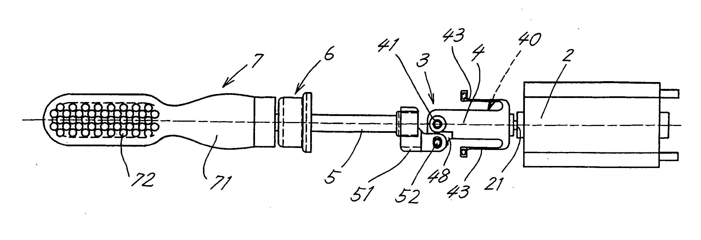
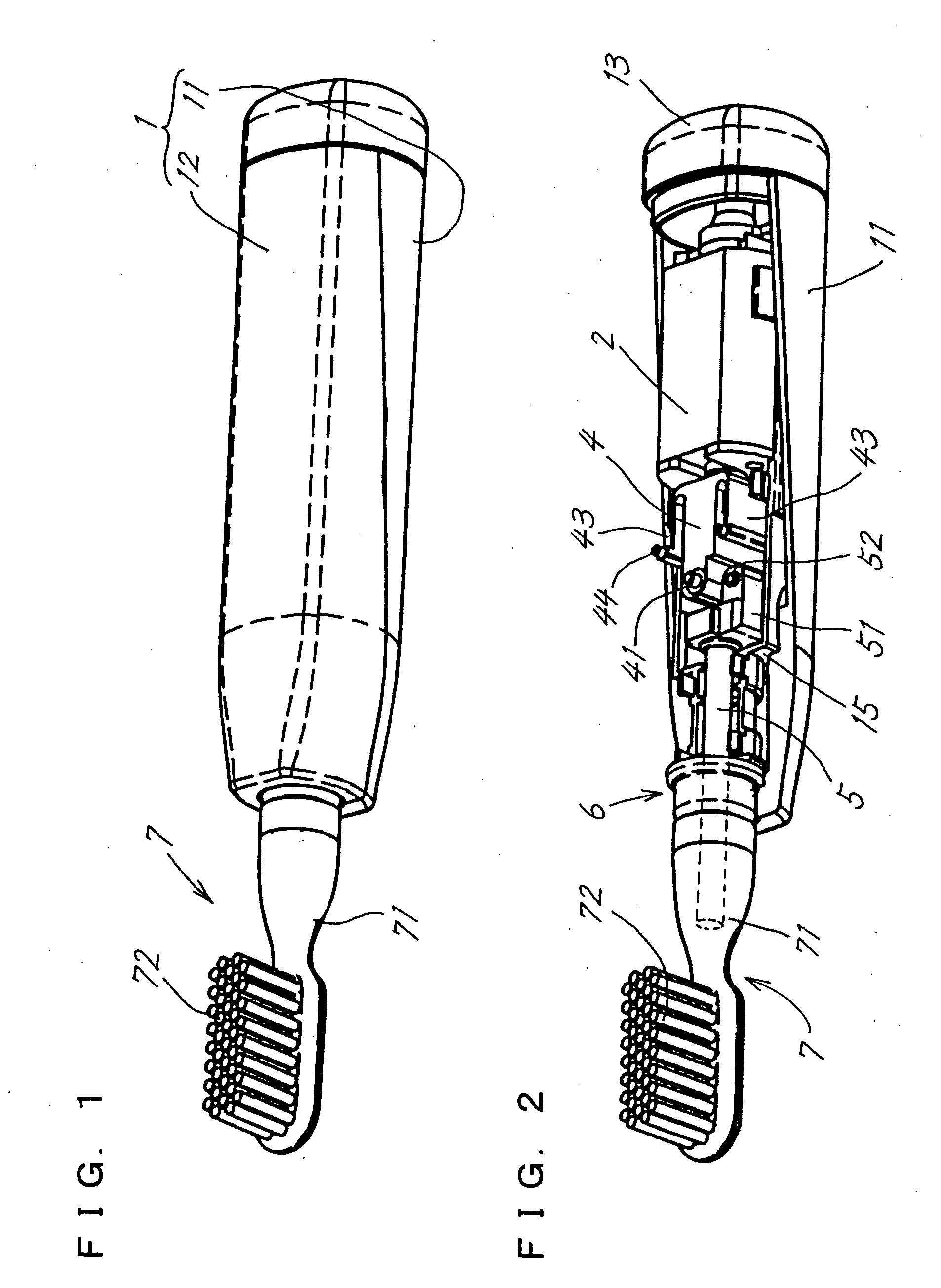
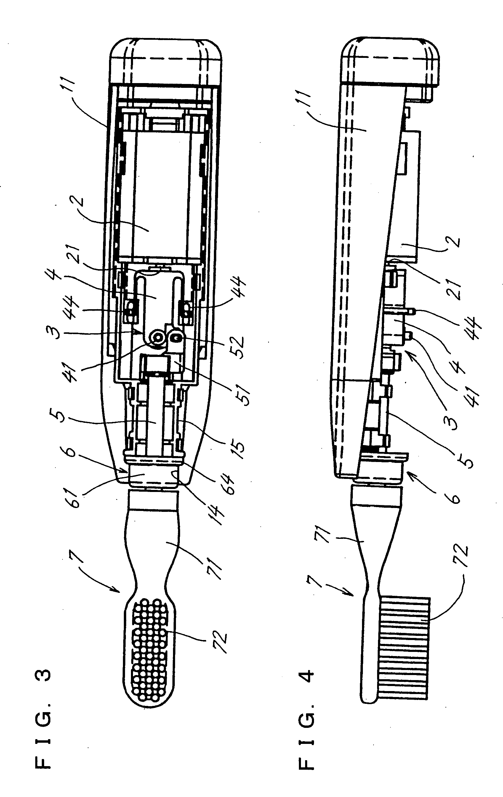
[0084] With the electric toothbrush one turn of rotation of the motor shaft 21 causes the scotch yoke mechanism 41 to reciprocatingly pivotally move the pivotal body 4 about the support rod 41 by one stroke, and one stroke movement of the body 4 also causes the reciprocating shaft 5 to perform one stroke of forward and backward movement. Thus, one turn of rotation of the motor shaft 21 causes the brush member 7 on the shaft 5 to perform one stroke of reciprocating movement. The reciprocating shaft 5 slidingly moves while slightly deflecting from the center of the spherical bearing 6a.

first embodiment

[0085] As in the case of the toothbrush of the first embodiment, it is unlikely that the frequency of reciprocating motion of the brush member 7 will become smaller than the number of revolutions of the motor shaft 21.

[0086] According to the present embodiment, the distance L1 between the support rod 41 of the pivotal body 4 and the pivot 51 for the reciprocating shaft 5 is 3.5 mm, the distance L2 from the support rod 41 to the scotch yoke mechanism 40 is 7 mm, the eccentricity L3 of the eccentric rotating body 23 is 0.7 mm, and the stroke of reciprocating motion of the brush member 7 is 0.7 mm.

[0087] When the flexible bearing 6 of the first embodiment is used as the bearing fro the reciprocating shaft 5 of the second embodiment, no problem will arise since the flexible bearing 6 permits the deflection of the shaft 5.


PUM


Abstract

An electric toothbrush wherein the number of revolution of a motor shaft is in match with the frequency of reciprocating motion of the brush. A motor (2) housed in a tubular case (1) is coupled to a reciprocating shaft (5) slidably extending through the forward end of the case by a scotch yoke mechanism (40) for converting one turn of rotation of the motor shaft (21) into one stroke of reciprocating pivotal movement of a pivotal body (4), and by motion conversion means (3) for converting one stroke of reciprocating movement of the pivotal body (4) into one stroke of linear reciprocating motion of the reciprocating shaft (5).

Description

FIELD OF THE INVENTION [0001] The present invention relates to electric toothbrushes for brushing teeth by the Bass method using a motor as a power source. BACKGROUND OF THE INVENTION [0002] With reference to FIGS. 16 and 17 showing an electric toothbrush for practicing the Bath method (reciprocating motion), the toothbrush comprises a tubular case 1 serving also as a handle, a motor 2 housed in the case 1 and having a motor shaft 21 extending along the axis of the case 1, and a reciprocating shaft 5 having a brush member 7 and reciprocatingly drivable by the rotation of the motor shaft 21 as converted into a linear movement approximately along the axis of the case 1 by motion conversion means. [0003] For example according to JP-A No. 9-24057 and JP-A No. 9-177923, a pinion gear 31 mounted on the motor shaft 21 is in mesh with a crown gear 32 perpendicular to the axis of the gear 31. A rotating shaft 33 for the crown gear 32 has mounted thereon an eccentric rotating body 34, which i...

Claims


Application Information

Patent Timeline
IPC IPC(8): A61C17/34
CPCY10T74/18032A61C17/3445
Inventor FUJIMOTO, NORIOKIKAMIMURA, TORUMATSUE, JUNJI
Owner SANYO ELECTRIC CO LTD
Learn More