Vacuum interface between a mini-environment pod and a piece of equipment

a technology of vacuum interface and mini-environment pod, which is applied in the field of transporting flats, can solve the problems of gas flow, particulate contamination of flat articles, and exposure to molecules present in the atmospher

Active Publication Date: 2006-05-18
ALCATEL LUCENT SAS
View PDF10 Cites 31 Cited by
  • Summary
  • Abstract
  • Description
  • Claims
  • Application Information

AI Technical Summary

Benefits of technology

[0064] The centering means provided in the pod door preferably have two housings corresponding to the centering means of the interface door. These housings are adapted to

Problems solved by technology

These changes in gas pressure require both pumping operations and operations of returning to atmospheric pressure to be performed, and those operations take time and lead to gas flows.
Such gas flows can move particles, thereby leading to particulate contamination of the flat articles.
Furthermore, when the flat article is at atmospheric

Method used


Image

  • Vacuum interface between a mini-environment pod and a piece of equipment
  • Vacuum interface between a mini-environment pod and a piece of equipment
  • Vacuum interface between a mini-environment pod and a piece of equipment

Examples


Embodiment Construction

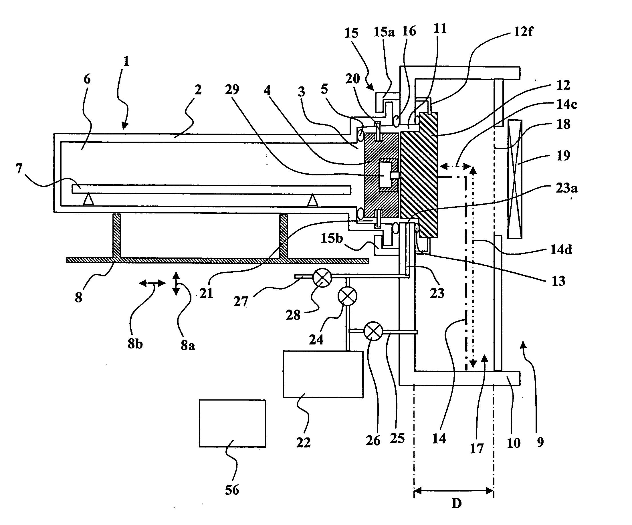
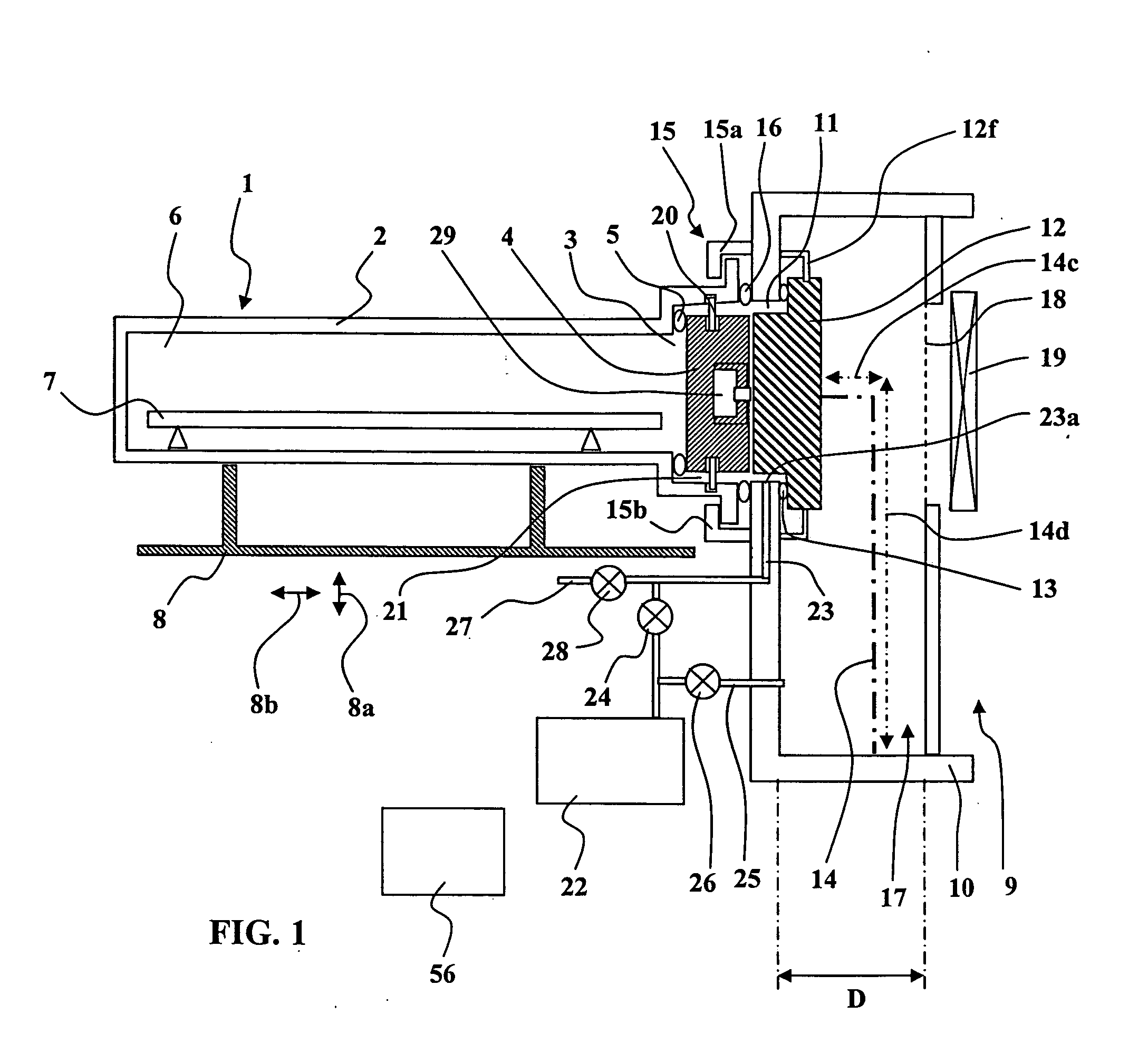
Reference is made initially to FIG. 1 which is a diagrammatic side view in longitudinal section of transport apparatus in an embodiment of the present invention.

[0080] There can be seen a transport pod 1 with an opening in a side wall, having a leakproof peripheral wall 2 and an inlet / outlet opening 3 that is closable by a pod door 4 associated with front sealing means 5 for the pod door.

[0081] The structure of the transport pod 1 must be mechanically strong in order to be capable of withstanding external atmospheric pressure in the presence of a vacuum in its internal cavity 6.

[0082] Inside the internal cavity 6, there is shown a flat article 7 such as a semiconductor wafer or a mask, placed in the transport pod 1 in order to be moved between two successive sites.

[0083] The transport pod 1 rests on a pod support 8 that is vertically and horizontally movable, as represented by arrows 8a and 8b.

[0084] There can also be seen a piece of equipment 9 having a leakproof peripheral w...


PUM


Abstract

In apparatus of the invention, a transport pod (1) can be coupled to an article-passing opening (11) of process equipment (9) in leaktight manner with sealing being provided by an interposed interface peripheral gasket (16). The pod door (4) can be secured selectively to the interface door (12) so that they can be moved together as a unit along an axial stroke followed by a transverse stroke under drive from door actuator means (14). The transport pod (1) is held by retaining means (15). The peripheral volume (21) around the two doors can be pumped out by means of a pump (22) and a duct (23). The pod door (4) can be locked on the transport door (1) by locking means (20) that guarantee good sealing while the transport pod (1) is separate from the process equipment (9). This ensures good sealing of the transport pod (1), and enables the doors (4, 12) to be opened under a vacuum without polluting the inside atmosphere.

Description

CROSS-REFERENCE TO RELATED APPLICATIONS [0001] This application is based on French Patent Application No. 0451932 filed 30 / 08 / 2004, the disclosure of which is hereby incorporated by reference thereto in its entirety, and the priority of which is hereby claimed under 35 U.S.C. §119. BACKGROUND OF THE INVENTION [0002] 1. Field of the Invention [0003] The present invention relates to transporting flat objects such as semiconductor wafers or masks between successive stages in a semiconductor fabrication process, the objects being transported in front-opening transport boxes, in particular in so-called front opening universal pods (FOUPs) that have a side opening, or in standard mechanical interface (SMIF) pods that have a bottom opening. [0004] 2. Description of the Prior Art [0005] Wafers and masks are commonly transported in FOUP or SMIF pods in order to protect wafers and masks against the residual pollution that is present, even in “clean” rooms. The transport pod isolates the wafer...

Claims


Application Information

Patent Timeline
IPC IPC(8): F03B11/02
CPCH01L21/67772Y10S414/137Y10T137/8593
Inventor LE GUET, CATHERINEDESBIOLLES, JEAN-PIERREKAMBARA, HISANORIGODOT, ERWANSYLVESTRE, RAPHAEL
Owner ALCATEL LUCENT SAS
Why Eureka
Try Eureka