
Raman detection based flow cytometer

a flow cytometer and raman technology, applied in the field of flow cytometers, can solve the problems of not being able to distinguish between similarly sized, but chemically different molecules or cells, and the raman spectrum of an individual particle in the flow cytometer is well beyond the realm of practicality, and achieves the effect of surface-enhanced raman scattering cross-section

Inactive Publication Date: 2006-05-18
HONEYWELL INT INC
View PDF12 Cites 14 Cited by
  • Summary
  • Abstract
  • Description
  • Claims
  • Application Information

AI Technical Summary

Benefits of technology

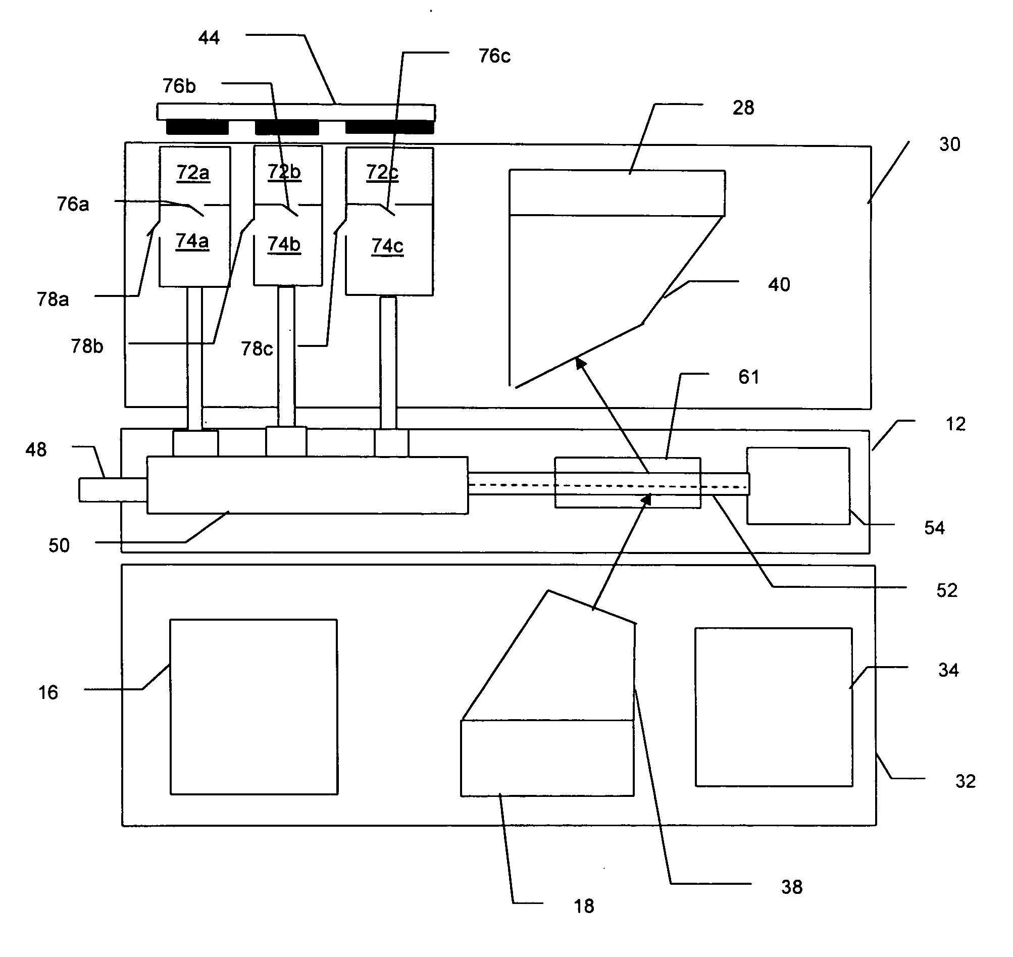
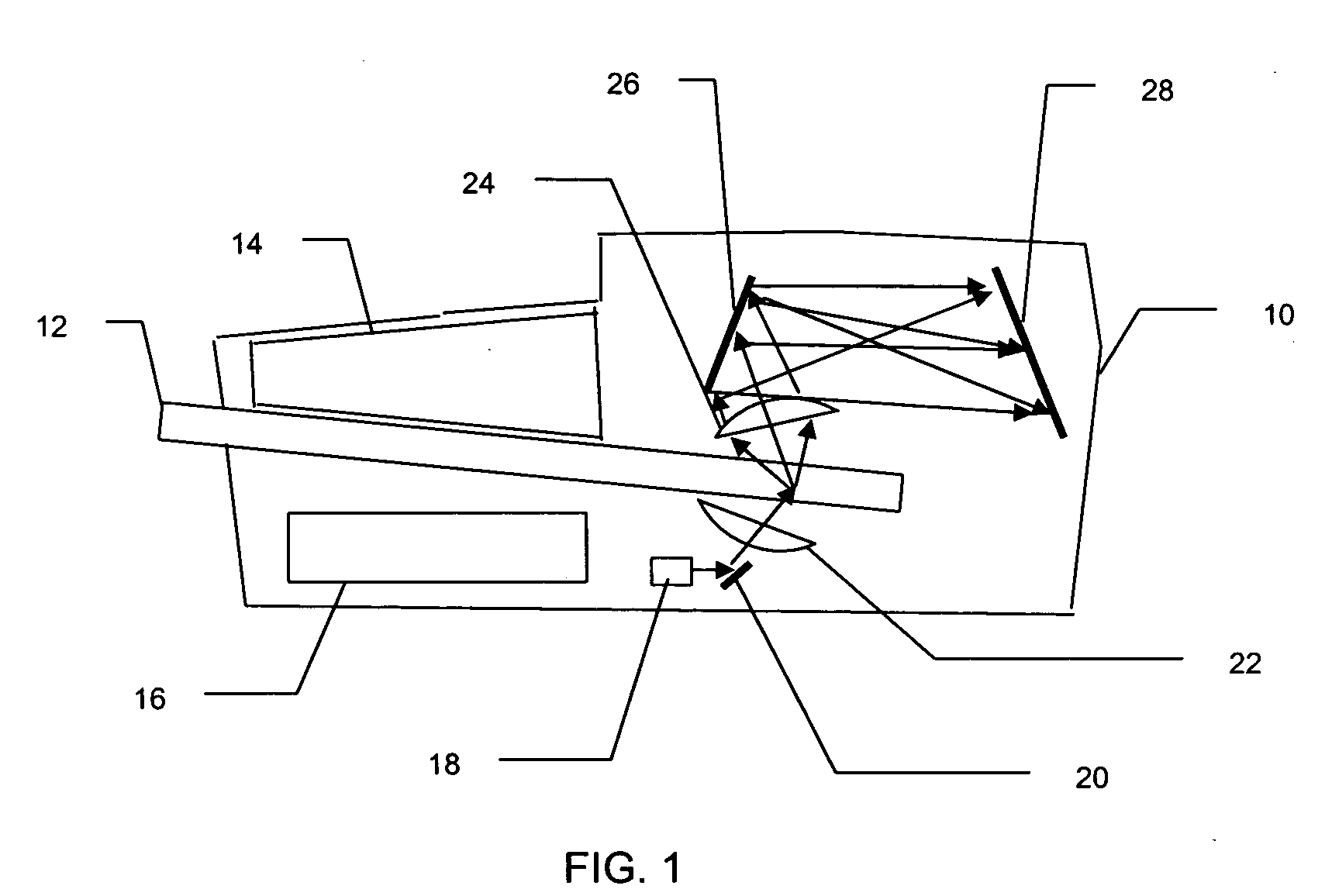
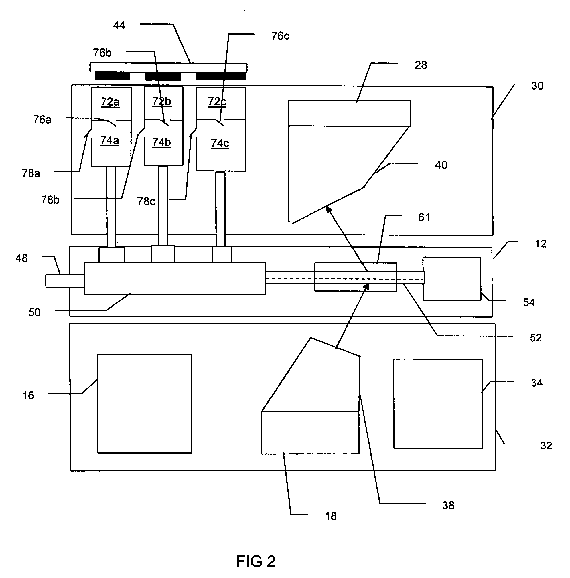
[0007] The present invention relates to methods and apparatus for enabling flow cytometers to identify individual particles primarily by means of their chemical or molecular structure. In a preferred embodiment of the invention, the chemical identification is achieved by obtaining a Raman spectrum of the particle, which may be an individual cell or molecule, as it flows past a sensing point in a flow cytometer. The particles are associated with a suitable noble metal colloid or colloidal aggregate so that their Raman scattering cross-section is surface-enhanced. The particles are then arranged in single file by a fluid control module capable of creating a hydrodynamically focused flow stream, and a light source illuminates each particle as it flows past a sensing point. Because the Raman cross-section is surface-enhanced, the light source may be a conventional laser. The light that is non-elastically scattered (Raman scattered) by the particle is gathered and the surface-enhanced Raman spectrum recorded using suitable dispersion optics and a suitable detector. The surface-enhanced Raman spectrum may then be analyzed to identify the particle from its molecular structure.

Problems solved by technology

Although such flow cytometers can identify the size and shape, they cannot differentiate between similarly sized, but chemically different molecules or cells, unless the molecules or cells have been tagged with fluorescent markers.
This means that obtaining the Raman spectrum of an individual particle in a flow cytometer is well beyond the realms of practicality because of the lack of a suitably intense light source and the lack of any suitably sensitive detectors.

Method used


Image

  • Raman detection based flow cytometer
  • Raman detection based flow cytometer
  • Raman detection based flow cytometer

Examples


Embodiment Construction

[0015] The Raman based flow cytometry of the present invention counts individually identified particles within a sample by combining non-destructive, molecule specific Raman spectroscopy with a flow cytometer's ability to sequentially observe individual molecules.

[0016] One difficulty in implementing Raman based flow cytometry is that Raman scattering has a very low cross-section, i.e., only a very small percentage of the photons in a light beam focused on a sample are Raman (in-elastically) scattered. The effective Raman cross-section of a sample may, however, be increased by the technique of surface enhanced Raman Scattering, in which each molecule is associated with a noble metal colloid or colloidal aggregate. This association can be done by, for instance, sonification of cells in a noble metal colloidal solution.

[0017] The cytometric technique of hydrodynamic focusing may then be used to arrange the prepared molecules in a single file, flowing as a core stream within a fluid ...


PUM

PropertyMeasurementUnit
wavelengthsaaaaaaaaaa
surface enhanced Raman spectrumaaaaaaaaaa
SERSaaaaaaaaaa

Abstract

A method and apparatus for enabling chemical identification of individual particles, cells of molecules by obtaining a Raman spectrum of a particle, cell or molecule as it flows past a sensing point in a flow cytometer. The particles, which may be cells or molecules, are associated with a suitable noble metal colloid or colloidal aggregate. Cellular particles may be associated with gold or silver colloidal particles by ultra-sonic sonification while in a sample preparation reservoir containing the gold or silver colloidal suspension. The colloid associated particles are then hydrodynamically focused into a single file by a fluid control module. The surface-enhance Raman Spectrum of individual particles are obtained by illuminating the particle with a laser as the particle flows past a sensing point and gathering the light that is non-elastically scattered (Raman scattered) by the particle. The surface-enhanced Raman spectrum is then analyzed to identify the particle.

Description

FIELD OF THE INVENTION [0001] The present invention relates generally to flow cytometers, and more particularly to portable flow cytometers that use surface-enhanced Raman spectroscopy to identify the specimens that are being counted. BACKGROUND OF THE INVENTION [0002] Flow cytometry is a well known means of measuring certain physical and chemical characteristics of cells or particles by sensing certain optical properties of the cells or particles as they travel in suspension, one by one past a sensing point. Flow cytometry is widely used in the biological and medical fields. [0003] In a typical flow cytometer, the single file flow of particles is achieved using hydrodynamic focusing of the suspended particles within a sheath fluid. The particles are then individually interrogated by a light beam. In most modern cytometers, the light source is a laser which emits coherent light at a specified wavelength. Each particle interacts with the light beam, and typically the scattered and an...

Claims


Application Information

Patent Timeline
Patent Type & Authority Applications(United States)
IPC IPC(8): G01J3/44G01N21/65
CPCG01N15/147G01N21/658
Inventor FRITZ, BERNARD S.PADMANABHAN, ARAVINDCABUZ, CLEOPATRA
Owner HONEYWELL INT INC
Learn More