Method to control point spread function of an image

a technology of image spread and control method, which is applied in the field of improved imaging technology, can solve the problems of slow response time and imprecise voltage control, hinder the ability of passive matrix, and inconvenient control of imprecise voltage, so as to save development time and cost, not to over blur the image, and to reduce contrast

Active Publication Date: 2006-05-18
APTIV TECH LTD
View PDF98 Cites 144 Cited by
  • Summary
  • Abstract
  • Description
  • Claims
  • Application Information

AI Technical Summary

Benefits of technology

[0066] The algorithm provides a procedure to preserve the image quality by the and abate more interference by the manipulation and optimization of the point spread function acting on the image caused by the spatial filter, and additionally provides a simple, timely means to do this in absence of a group of observers and at the soft prototype stage.
[0080] According to yet another aspect of the present invention point spread function can be soft and hard prototyped and moiré interference abated; whilst maintaining image quality.

Problems solved by technology

The passive matrix system has significant drawbacks, notably slow response time and imprecise voltage control.
Imprecise voltage control hinders the passive matrix's ability to influence only one pixel at a time.
When voltage is applied to change the optical state of one pixel, the pixels around it also partially change, which makes images appear un-sharp and lacking in contrast.
However while this may help remove moiré it has the effect of changing the bidirectional scattering transmission function of the sub-pixels, smearing them to a point spread function thus effectively reducing the resolution of the display.
A similar pattern is available on a non-birefringent surface such as acrylic but this substrate cannot be made thin enough as not over-blur the rear most pixels.
In general one cannot easily control the angular distribution of the light as it exits a typical diffuser.
Also because there is an extra layer in the optical stack, extra air-plastic or air-glass interfaces are formed causing back reflections.
This reflected light may also be re-reflected out to the viewer, but may not appear to come from the correct origin, reducing the contrast of the display.
Also because the film is on a separate sheet it has the tendency to deform due to the heat from the high-brightness backlight which is visible to the viewer and can exasperate the sharpness problem described above.

Method used


Image

  • Method to control point spread function of an image
  • Method to control point spread function of an image
  • Method to control point spread function of an image

Examples


Embodiment Construction

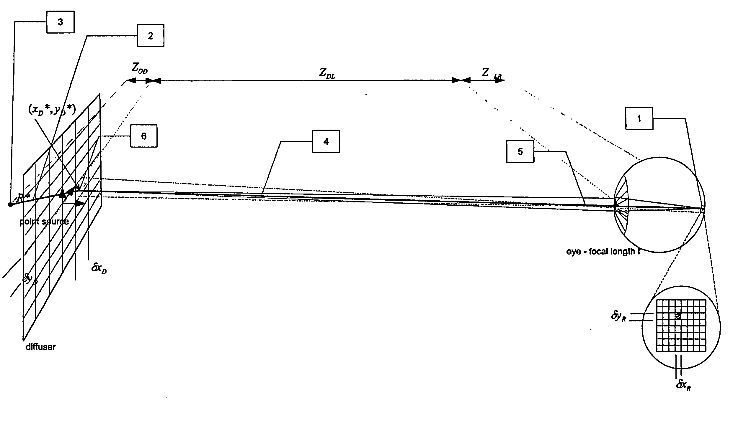
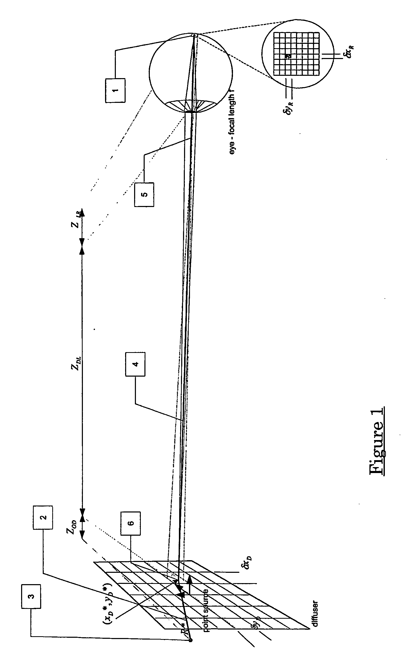
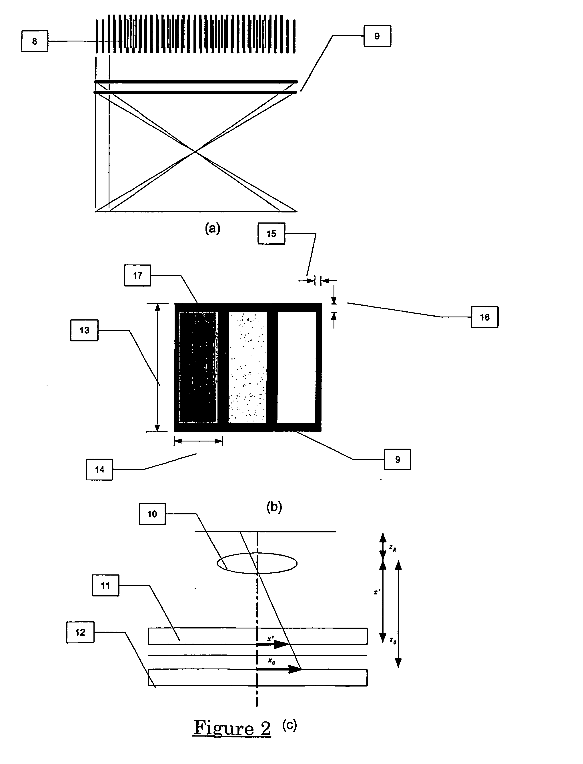
[0094] At present there exist methods to produce displays where several imaging planes are stacked with set distances between them. These imaging planes may also be stacked as closely as possible. These displays consist of a high-brightened backlight, a rear image panel which is usually an active matrix, colour display, a diffuser and a front image plane, which are laminated to form a stack. There are generally colour filter stripes, and a black matrix on each display which defines the borders of the pixels. However it should be appreciated that the following discussion applies to all addressable object planes that are addressed by passive or active matrices or have colour filters, or any periodic pattern. For the purposes of the present invention these addressable object planes may not be addressable at all.

[0095] It is an object of the present invention to address the foregoing problems or at least to provide the public with a useful choice.

Further aspects and advantages of the...


PUM

PropertyMeasurementUnit
wavelengthaaaaaaaaaa
elliptical anglesaaaaaaaaaa

Abstract

A method of controlling the point spread function of an image projected with said image being diffused by a filter; said point spread function is a result of the application of spatial filter(s) on said image; with said control of the point spread function effected by varying the distance between such image and said spatial filter(s) and varying the bidirectional scattering transmission function of the spatial filter(s). Said spatial filter may be a holographic diffuser, which by method of manufacture has a ell defined bi-directional scattering transmission spread function. Control of said spread function is particularly useful to maintain image quality while abating moiré interference in situations where two periodic patterns are layered causing moiré interference.

Description

TECHNICAL FIELD [0001] This invention relates to the field of improved imaging technology. In particular, this invention will be discussed in relation to display technology with multiple image layers. [0002] Reference shall now be made to use of the present invention in relation to multiple layered display technology. BACKGROUND ART [0003] There are two main types of displays used in computer monitors, passive matrix and active matrix. Passive-matrix displays use a simple grid to supply the charge to a particular pixel on the display. Creating the grid starts with two glass layers called substrates. One substrate is given columns and the other is given rows made from a transparent conductive material. This is usually indium tin oxide. The rows or columns are connected to integrated circuits that control when a charge is sent down a particular column or row. The electro-optical material is often sandwiched between the two glass substrates. [0004] A pixel is defined as the smallest re...

Claims


Application Information

Patent Timeline
Patent Type & Authority Applications(United States)
IPC IPC(8): G02B3/00G02B5/32G02B27/46G02F1/1335H04N5/74
CPCG02B27/46G02F1/133504
Inventor BELL, GARETH PAULENGEL, GABRIEL DAEMONSEARLE, MARK JOHNEVANICKY, DANIEL
Owner APTIV TECH LTD
Why Eureka
Try Eureka