
Method for restoring truncated helical cone-beam computed tomography data

a computed tomography and helical cone technology, applied in the field of restoring asymmetrically truncated imaging data, can solve the problems of asymmetric truncation, no new developments to take into account the cone angle with regard to the weighting function, and the uncertainty of the truncation level of often inevitable truncation, etc., to achieve the effect of redundancy of asymmetrically measured data

Inactive Publication Date: 2006-05-18
TOSHIBA MEDICAL SYST CORP
View PDF4 Cites 28 Cited by
  • Summary
  • Abstract
  • Description
  • Claims
  • Application Information

AI Technical Summary

Benefits of technology

[0030] Moreover, there is provided a computed tomography (CT) system to compensate for the unavailability of projection data of a scanned object at a selected point, the selected point located outside a detection range of a detector, comprising: (1) an X-ray source configured to project X-rays at a scanned object; (2) an asymmetric CT detector configured to detect said X-rays and to generate helical cone-beam CT projection data of the scanned object; and (3) a compensating processor configured to compensate for the unavailability of the projection data at said selected point based on the generated projection data and coordinates of the selected point relative to the CT detector.

Problems solved by technology

As a consequence, a certain level of truncation is often inevitable.
The small one, represented by the solid circle, is fully covered and the large one, represented by the dashed circle, cannot fully be covered and leads to asymmetric truncation.
However, even though such an idea was applied to helical cone-beam geometry, no new developments to take into account the cone angle with regard to the weighting function are known.
Moreover, the method of Wang cannot be used with short-scan reconstruction algorithms since it requires the entire revolution of data.

Method used


Image

  • Method for restoring truncated helical cone-beam computed tomography data
  • Method for restoring truncated helical cone-beam computed tomography data
  • Method for restoring truncated helical cone-beam computed tomography data

Examples


Embodiment Construction

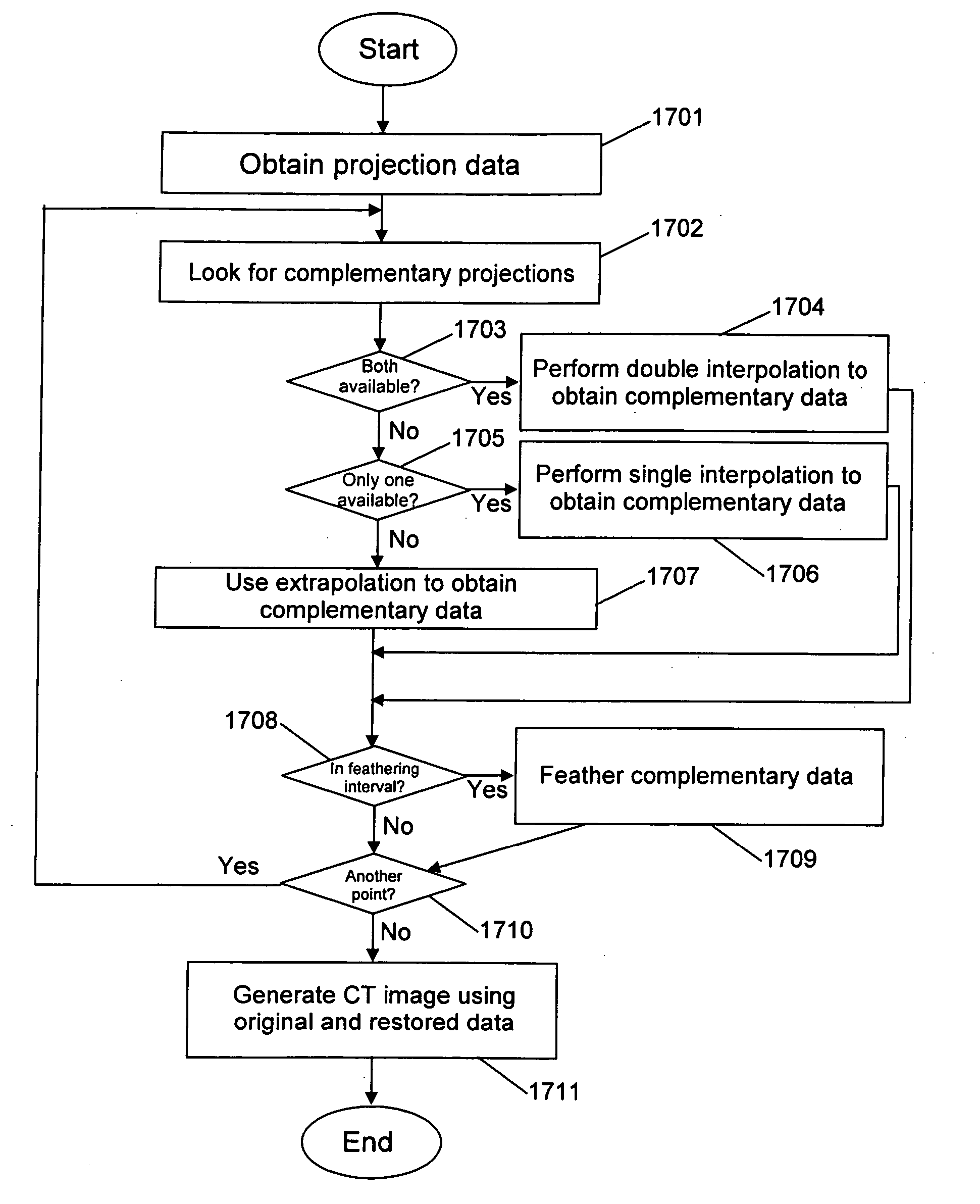
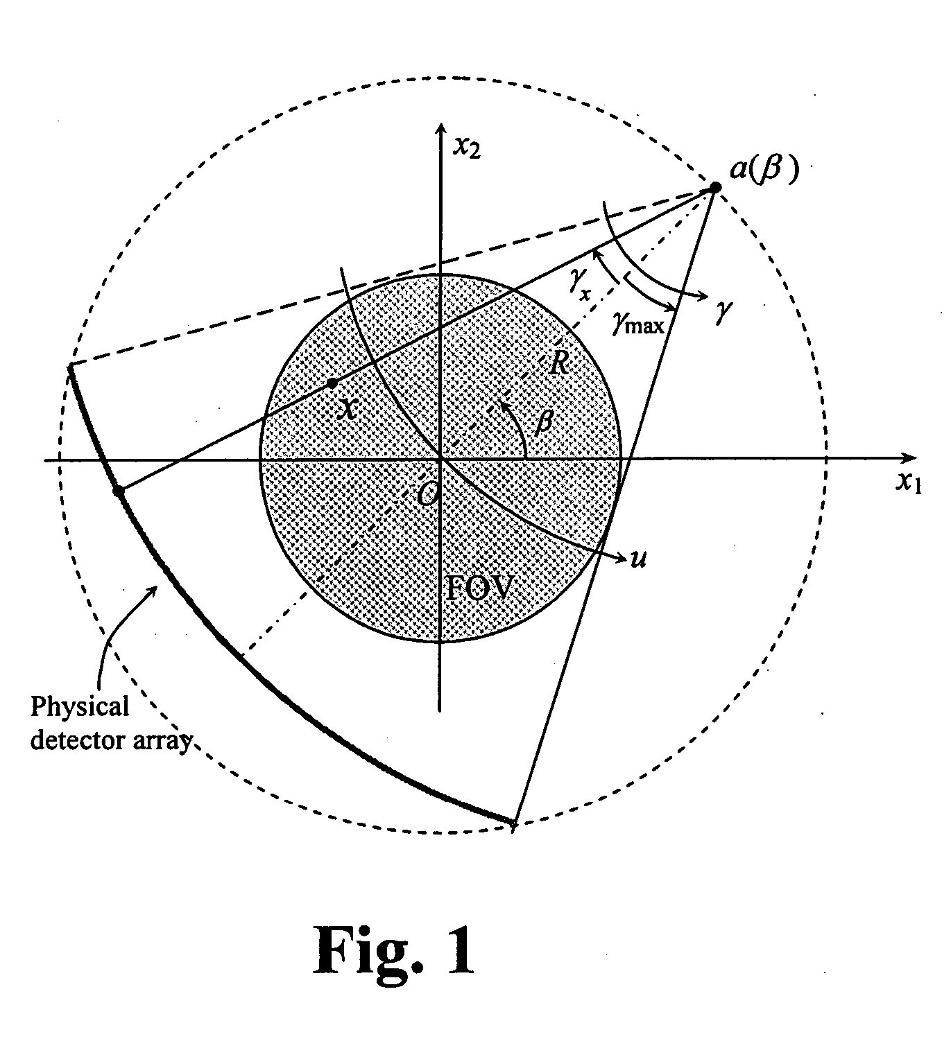
[0055]FIG. 5 illustrates the notion of a complementary ray. A fan beam ray (β,γ) has a complementary ray (β+π+2γ,−γ) such that g(β,γ)=g(β+π+2γ, −γ). Suppose that fan beam data are available and that the entire FOV that would be needed to fully cover the object, g(β,γ), β>0, −γmax≦γ≦γmax, exceeds the detector angular range. For instance, there might be a truncation area corresponding to γT≦γ≦γmax, γT>0 while the data are known for −γmax≦γ≦γT. See, e.g., FIG. 4. It follows that for a truncated ray (β0,γ0) with γT≦γ0≦γmax, the complementary ray (β0C,γ0C)=(β0+π+2γ0,−γ0) is known since −γmax≦γ0C≦−γT.

[0056] The projection angles β±π+2γ are called complementary to the ray (β,γ). For a circular geometry, it does not matter from a purely geometrical standpoint which complementary projection is used since g(β+π+2γ,−γ)=g(β−π+2γ,−γ). However, it turns out in practice that using a weighted sum of both complementary projections, e.g., g(β,γ)=w1g(β+π+2γ,−γ)+w2g(β−π+2γ,−γ), where w1, w2>0 and w1+w...


PUM


Abstract

A method, system, and computer program product for compensating for the unavailability of projection data of a scanned object at a selected point, the selected point located outside a detection range of a detector. The method include the steps of obtaining projection data of the scanned object, and compensating for the unavailability of the projection data at the selected point based on the obtained projection data and coordinates of the selected point relative to the detector. The compensating step includes determining at least one complementary projection angle and coordinates of at least one complementary point based on a source projection angle and the coordinates of the selected point relative to the detector, and estimating the projection data value at the selected point based on the acquired projection data, the at least one complementary projection angle, and the coordinates of the at least one complementary point.

Description

BACKGROUND OF THE INVENTION [0001] 1. Field of the Invention [0002] The present invention is directed to the restoration of asymmetrically truncated imaging data. More precisely the present invention relates to methods for restoring truncated helical cone-beam computed tomography (CT) data when truncation occurred as a result of displacing the detector so that its field of view (FOV) fully covers an oversized object. [0003] The present invention includes the use of various technologies referenced and described in the documents identified in the following LIST OF REFERENCES, which are cited throughout the specification by the corresponding reference number in brackets: [0004] List of References [0005] [1] P. E. Danielsson, P. Edholm, J. Eriksson and M. Seger, Towards exact 3D-reconstruction for helical cone-beam scanning of long objects. A new detector arrangement and a new completeness condition, Proc. on Fully 3D Image Reconstruction in Radiology and Nuclear Med., 141-144, 1997. [0...

Claims


Application Information

Patent Timeline
IPC IPC(8): H05G1/60A61B6/00G01N23/00G21K1/12
CPCG06T11/005G06T2211/432A61B6/027Y10S378/901
Inventor ZAMYATIN, ALEKSANDR A.TAGUCHI, KATSUYUKISILVER, MICHAEL D.
Owner TOSHIBA MEDICAL SYST CORP
Learn More