Power device

a power device and power supply technology, applied in the direction of coupling device connection, cell components, sustainable manufacturing/processing, etc., can solve the problems of reduced coupling strength of coupling a bus bar b>83/b> to a cell b>81/b>, electrical contact state of the bus bar and the connecting terminal cannot be brought into an ideal state, etc., to achieve mass production and great torque

Active Publication Date: 2006-05-18
SANYO ELECTRIC CO LTD
View PDF2 Cites 86 Cited by
  • Summary
  • Abstract
  • Description
  • Claims
  • Application Information

AI Technical Summary

Benefits of technology

[0013] The power device described above has a feature that the connecting terminal can have such a structure as to be mass-produced inexpensively, and furthermore, the bus bar and the connecting terminal can be coupled in a firm and strong structure. The reason is as follows. In the power device according to the present invention, the fixing plate portion in which the connecting terminal for connecting the bus bar to the cell is welded and fixed to the end of the cell is provided with the outer cylindrical portion, the end face plate portion and the inner cylindrical portion, the female screw is provided on the internal surface of the inner cylindrical portion and the setscrew is screwed into the same portion to couple the bus bar, the fixing plate portion in which the connecting terminal is welded and fixed to the end of the cell is provided with the outer cylindrical portion and the end face plate portion and the setscrew is screwed into the nut provided on the inside of the end face plate portion to couple the bus bar, or the fixing plate portion in which the connecting terminal is welded and fixed to the end of the cell is provided with the screw cylinder portion and the male screw is provided on the outside surface of the screw cylinder portion, and the screw cylinder portion is inserted in the through hole of the bus bar and the nut is screwed into the tip portion to fix the bus bar to the connecting terminal. By these structures, a large number of threads are provided on the female screw disposed in the inner cylindrical portion or the female screw of the nut disposed on the inside of the end face plate portion so that the setscrew can be fastened with a great torque, and furthermore, a large number of threads are provided on the male screw disposed in the screw cylinder portion so that the nut can be fastened with a great torque. The connecting terminal having the above structure can screw the setscrew into the inner cylindrical portion or the female screw of the nut with a great torque or the nut can be screwed into the screw cylinder potion with a great torque so that the bus bar can be firmly fixed to the connecting terminal. Consequently, it is possible to fasten the setscrew and the nut with a great torque and to strongly press the bus bar against the connecting terminal in a large area, and coupling them firmly.
[0014] In the power device in which the fixing plate portion is provided with the outer cylindrical portion, the end face plate portion and the inner cylindrical portion, and the female screw is provided on the internal surface of the inner cylindrical portion and the setscrew to penetrate through the bus bar is screwed into the female screw, and coupling the bus bar to the connecting terminal, moreover, the end face plate portion for coupling the bus bar through the setscrew and the inner cylindrical portion is coupled to the fixing plate portion through the outer cylindrical portion. The outer cylindrical portion takes a cylindrical shape and couples the whole periphery of the end face plate portion to the fixing plate portion. Consequently, the end face plate portion is coupled to the fixing plate portion in a firm and strong structure. Accordingly, the bus bar is firmly coupled to the end face plate portion through the setscrew, and furthermore, the end face plate portion is firmly coupled to the fixing plate portion through the outer cylindrical portion. Consequently, the bus bar is coupled to the end face of the cell through the connecting terminal in a strong structure.
[0015] In the power device in which the fixing plate portion is provided with the outer cylindrical portion and the end face plate portion, the nut is disposed on the inside of the end face plate portion and the setscrew to penetrate through the bus bar and the fixing plate portion is screwed into the nut to couple the bus bar to the connecting terminal, furthermore, the end face plate portion for coupling the bus bar through the setscrew and the nut is coupled to the fixing plate portion at the outer cylindrical portion. Consequently, the setscrew can be fastened to the nut with a great torque, and coupling the bus bar to the connecting terminal firmly. Furthermore, the outer cylindrical portion takes a cylindrical shape and couples the whole periphery of the end face plate portion to the fixing plate portion. Consequently, the end face plate portion is coupled to the fixing plate portion in a firm and strong structure. Accordingly, the bus bar is firmly coupled to the end face plate portion through the setscrew and the nut, and furthermore, the end face plate portion is firmly coupled to the fixing plate portion through the outer cylindrical portion and the bus bar is thus coupled to the end face of the cell through the connecting terminal in a strong structure.

Problems solved by technology

However, there is a drawback that a coupling strength for coupling a bus bar 83 to a cell 81 is reduced.
Furthermore, the setscrew cannot be fastened with a sufficiently great torque.
Consequently, there is also a drawback that an electrical contact state of the bus bar and the connecting terminal cannot be brought into an ideal state.

Method used


Image

  • Power device
  • Power device
  • Power device

Examples


Embodiment Construction

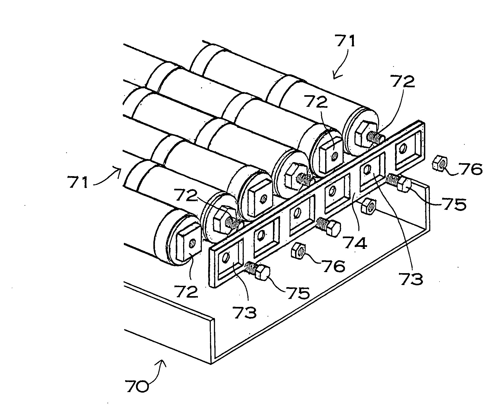
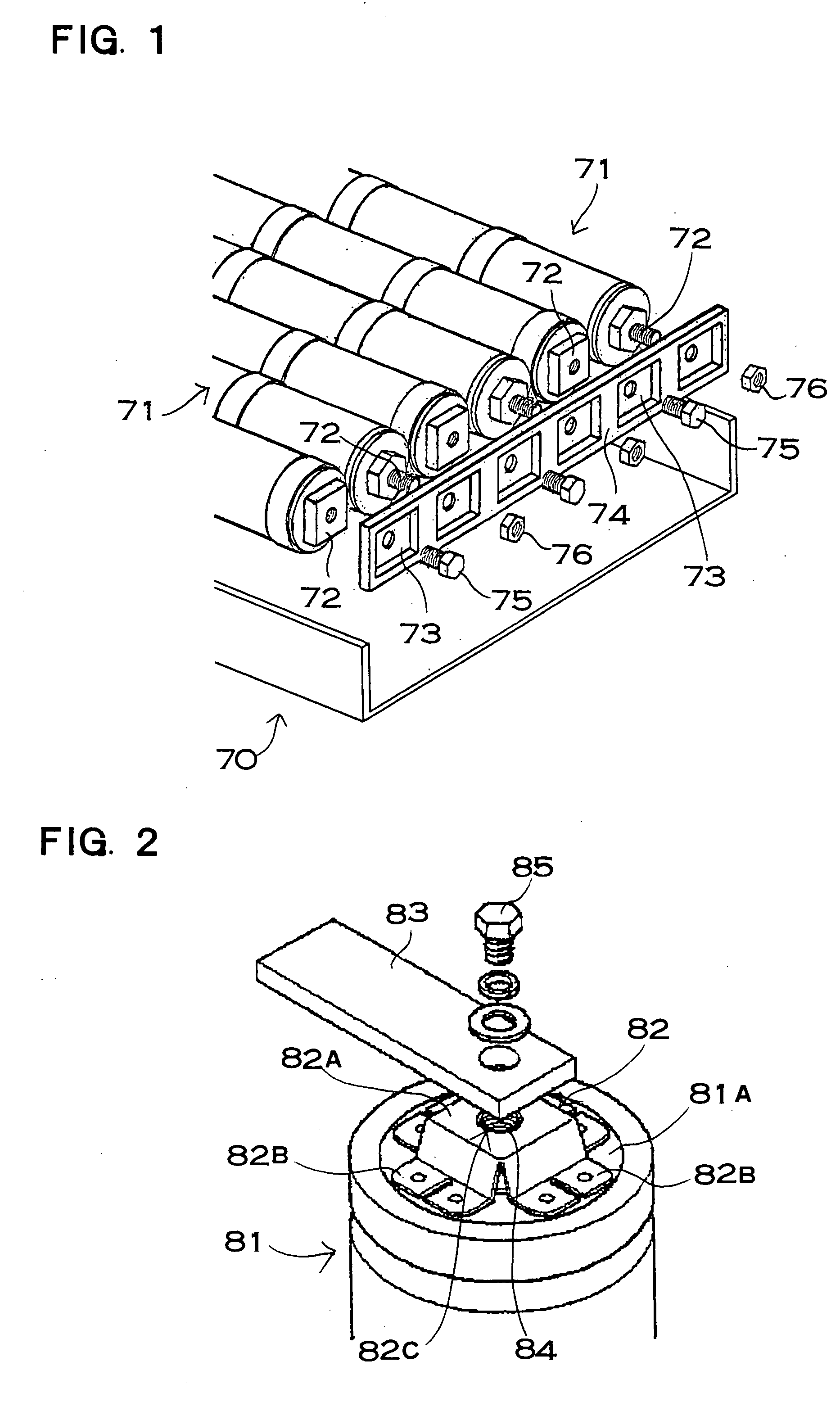
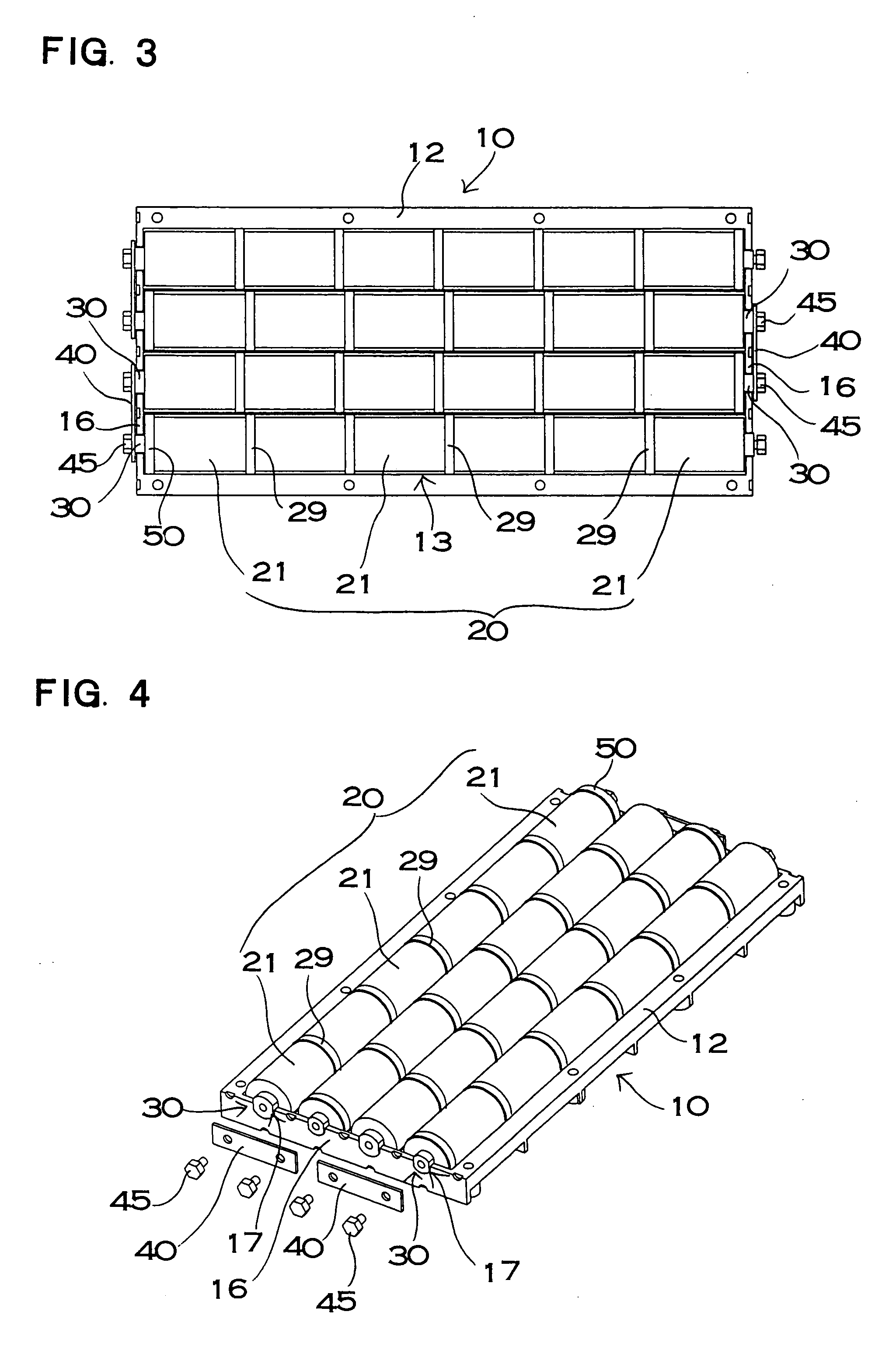
[0047] In a power device shown in FIGS. 3 to 6, a plurality of battery modules 20 in which a plurality of cells 21 is coupled rectilinearly is accommodated in a case 10 and the adjacent battery modules 20 are connected in series through a bus bar 40. The case 10 includes an upper case 11 and a lower case 12. FIG. 3 is a plan view excluding the upper case, FIG. 4 is an exploded perspective view showing the bus bar 40 and a setscrew 45, FIG. 5 is an exploded perspective view in which the battery module 20 is attached to the case 10, and FIG. 6 is a longitudinal sectional view. A power device shown in these drawings is mainly used for an electrically-powered vehicle such as a hybrid car, an electric car or a fuel cell car. The power device according to the present invention can also be used to meet a demand for a large output in addition to the electrically-powered vehicle. In the battery module 20 in the drawings, the secondary cells 21 to be cylindrical cells are coupled rectilinearl...


PUM

PropertyMeasurementUnit
thicknessaaaaaaaaaa
thicknessaaaaaaaaaa
thicknessaaaaaaaaaa

Abstract

A power device includes a battery module for fixing a connecting terminal to an end and a bus bar connected to the connecting terminal of the battery module. The connecting terminal includes a fixing plate portion fixed to the end of the cell, an outer cylindrical portion protruded cylindrically from the fixing plate portion, an end face plate portion closing a tip surface of the outer cylindrical portion, and an inner cylindrical portion protruded from the end face plate portion toward the fixing plate portion. The connecting terminal is provided with a female screw on an internal surface of the inner cylindrical portion and a setscrew penetrating through the bus bar is screwed toward the female screw, and the bus bar is fixed to the connecting terminal through the setscrew.

Description

BACKGROUND OF THE INVENTION [0001] 1. Field of the Invention [0002] The present invention relates to a power device to be mainly mounted on an electrically-powered vehicle such as a hybrid car, a fuel cell car or an electric car. [0003] 2. Description of the Related Art [0004] A power device in which a plurality of cells to be secondary cells is coupled rectilinearly to form a battery module and a plurality of battery modules is further connected is used to meet a demand for a large output as in an electrically-powered vehicle. In the power device of this type, a case 70 accommodates a battery module 71 as shown in FIG. 1. The battery module 71 to be accommodated in the case 70 has both ends to which a connecting terminal 72 formed by a screw and a nut is fixed. The battery module 71 fixes a bus bar 73 to the connecting terminal 72 and is connected in series through the bus bar 73. The case 70 has a side portion provided with an end plate 74 including the bus bar 73. The end plate 7...

Claims


Application Information

Patent Timeline
Patent Type & Authority Applications(United States)
IPC IPC(8): H01R3/00H01M50/505H01M50/51H01M50/517H01M50/522H01M50/528H01M50/559H01M50/566
CPCH01M2/202H01M2/30H01R31/085Y02E60/10Y02P70/50H01M50/522H01M50/559H01M50/517H01M50/51H01M50/505H01M50/566H01M50/20H01M50/528
Inventor YOSHIKANE, TAKETOSHIOCHI, SHINGO
Owner SANYO ELECTRIC CO LTD
Why Eureka
Try Eureka