Method for producing metal-carbon fiber composite material

a technology of metal-carbon fiber and composite materials, which is applied in the direction of coatings, layered products, chemistry apparatus and processes, etc., can solve the problems of large production equipment and complicated production work, and achieve the effect of ensuring the uniformity of the physical properties of the composite material in the planar direction, reducing production costs, and increasing thermal conductivity of the obtained composite material

Inactive Publication Date: 2019-01-03
SHOWA DENKO KK
View PDF1 Cites 1 Cited by
  • Summary
  • Abstract
  • Description
  • Claims
  • Application Information

AI Technical Summary

Benefits of technology

[0038]In the aforementioned Item [1], by adopting the steps of applying a coating liquid on a surface of a metal foil, forming a laminate in a state in which a plurality of coated foils is laminated, and integrally joining the coated foils by pressurizing and heating the laminate, a metal-carbon fiber composite material can be inexpensively mass-produced.
[0039]Furthermore, by removing the binder from the laminate, the thermal conductivity of the obtained composite material can be assuredly increased.
[0040]Furthermore, by configuring such that the coating apparatus for applying a coating liquid on the surface of the metal foil is the gravure coating device, the cell shape of the gravure roll of the gravure coating device is a cup shape, and the diameter of the circle inscribed in the mouth shape of the cell is set to 1.2 times or more the average fiber length of the carbon fiber, a carbon fiber layer can be formed on the surface of the metal foil so that the fiber directions of the carbon fibers in the surface of the metal foil become random. For this reason, the physical properties of the composite material in the planar direction can be equalized. Moreover, it is unnecessary to consider the fiber directions of the carbon fibers when forming the laminate, so that the physical properties of the composite material in the planar direction can be easily equalized.
[0041]In the aforementioned Item [2], by removing the solvent from the carbon fiber layer, it is possible to satisfactorily integrally join the coated foils in the step of integrally joining the coated foils.
[0042]In the aforementioned Item [3], by not subjecting the surface of the carbon fiber layer to slide leveling processing, the fiber directions of the carbon fibers in the carbon fiber layer can be maintained in a random state. As a result, uniformity of the physical properties of the composite material in the planar direction can be attained assuredly.
[0043]In the aforementioned Item [4], the production of the composite material can be easily performed by removing the binder from the laminate in the middle of heating the laminate so that the temperature of the laminate rises to the temperature at which the coated foils are integrally joined.

Problems solved by technology

However, with these methods, since molten aluminum or aluminum powder is used, the production work was complicated and the producing equipment was large.

Method used


Image

  • Method for producing metal-carbon fiber composite material
  • Method for producing metal-carbon fiber composite material
  • Method for producing metal-carbon fiber composite material

Examples


example 1

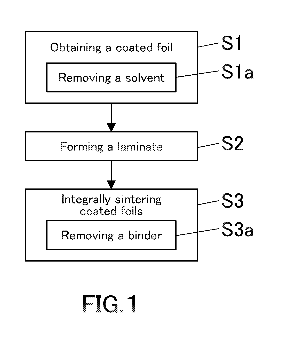
[0171]In Example 1, an aluminum-carbon fiber composite material was produced by the following procedure.

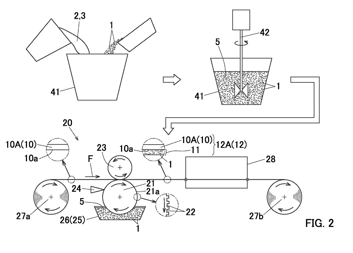
[0172]Carbon fibers having an average fiber length of 150 μm and an average fiber diameter of 10 μm (XN-100 manufactured by Nippon Graphite Fiber Co., Ltd.), a 3 mass % aqueous solution of polyethylene oxide (Alcox (registered trademark) E-45 manufactured by Meisei Chemical Industry Co., Ltd.) having an average molecular weight of 700,000 as a binder, an isopropyl alcohol as a solvent, water, a dispersant, and a surface conditioner were stirred and mixed, whereby a coating liquid was obtained. The mass of the binder contained in the coating liquid was 10% in terms of solid contents with respect to the mass of carbon fibers. The viscosity of the coating liquid was 1,000 mPa·s at 25° C.

[0173]The coating liquid was applied to the entire lower surface of a belt-like strip member of an aluminum foil (its material: A1N30) having a thickness of 20 μm and a width of 500 mm by a gravure co...

example 2

[0184]In Example 2, an aluminum-carbon fiber composite material was produced by the following procedure.

[0185]Carbon fibers having an average fiber length of 200 μm and an average fiber diameter of 10 μm (K223HM manufactured by Mitsubishi Plastics, Inc.), an acryl based resin as a binder, a propylene glycol ethyl ether acetate as a solvent, a dispersant, and a surface conditioner were stirred and mixed. Thus, a coating liquid was obtained. The mass of the binder contained in the coating liquid was 20% in terms of solid contents with respect to the mass of carbon fibers. The viscosity of the coating liquid was 700 mPa·s at 25° C.

[0186]The coating liquid was applied to the entire lower surface of the belt-like strip member of the aluminum foil (its material: A1N30) having a thickness of 20 μm and a width of 280 mm by a gravure coater at a coating rate of 30 m / min. With this, a coated foil strip member with a carbon fiber layer formed on the lower surface of the aluminum foil strip mem...


PUM

PropertyMeasurementUnit
diameteraaaaaaaaaa
lengthaaaaaaaaaa
lengthaaaaaaaaaa

Abstract

A method for producing a metal-carbon fiber composite material includes the steps of: obtaining a coated foil (12) in which a carbon fiber layer (11) is formed on a surface (10a) of a metal foil (10) by applying a coating liquid (5) containing carbon fibers (1), etc., on the surface (10a) of the metal foil (10) with a gravure coating device (20); forming a laminate in which a plurality of coated foils (12) is laminated; and integrally joining the coated foils (12) by heating while pressurizing the laminate in a lamination direction of the coated foils (12). The shape of a cell (22) of a circumferential surface (21a) of a gravure roll (21) of the gravure coating device (20) is a cup shape and a diameter of a circle inscribed in a mouth shape of the cell (22) is set to 1.2 times or more the average fiber length.

Description

FIELD OF THE INVENTION[0001]The present invention relates to a method for producing a metal-carbon fiber composite material and a method for producing an insulating substrate.[0002]In this specification and appended claims, the term “aluminum” is used to mean both pure aluminum and an aluminum alloy unless otherwise specified, and in the same manner, the term “copper” is used to mean both pure copper and a copper alloy unless otherwise specified.[0003]A vertical direction of an insulating substrate according to the present invention is not limited. However, in this specification and appended claims, for the purpose of facilitating the understanding of the configuration of the insulating substrate, the mounting surface side of the insulating substrate on which a heat generating element is mounted is referred to as the upper side of the insulating substrate, and the opposite side thereof is referred to as the lower side of the insulating substrate.BACKGROUND ART[0004]As a material imp...

Claims


Application Information

Patent Timeline
Patent Type & Authority Applications(United States)
IPC IPC(8): B32B37/15B32B15/08B32B15/20B32B37/10B32B38/00B05D1/28
CPCB32B37/15B32B15/08B32B15/20B32B37/10B32B38/0036B05D1/28B32B2307/304B32B2262/106B32B2255/06B32B2255/26C22C47/06C22C47/20C22C49/06C22C49/14
Inventor MIZO, TATSUHIRO
Owner SHOWA DENKO KK
Why Eureka
Try Eureka