
Testing methods and apparatus for wireless communications

a wireless communication and test method technology, applied in electrical equipment, transmission, transmission monitoring, etc., can solve the problems of limited test functionality provided by the audio coupler, limited conventional testing methods described above, and insufficient accessibility, so as to facilitate the telephone call connection

Inactive Publication Date: 2006-05-18
AT&T MOBILITY II LLC
View PDF12 Cites 7 Cited by
  • Summary
  • Abstract
  • Description
  • Claims
  • Application Information

AI Technical Summary

Benefits of technology

"The patent describes a computer test station that can test the operation of wireless telephone units in a wireless communication system. The test station is located remotely from the wireless units and receives calls from them using an abbreviated dialing number. The test station assigns security to the calls and executes a predetermined test function based on the caller's information. The test results are stored and associated with the caller's information for easy analysis. The technical effects of this invention include improved testing efficiency and accuracy, as well as simplified troubleshooting of call issues in wireless communication systems."

Problems solved by technology

The conventional testing methods described above are limited.
Only a particular type of cellular telephone can operate in connection with the laptop computer and its software, and multiple cellular telephones at different geographic locations cannot be simultaneously tested by it.
The testing methods using the audio coupler are more flexible since a number of different types of cellular telephones may access it; however, this provides too much accessibility.
In addition, the test functionality provided by the audio coupler is limited.

Method used


Image

  • Testing methods and apparatus for wireless communications
  • Testing methods and apparatus for wireless communications
  • Testing methods and apparatus for wireless communications

Examples


Embodiment Construction

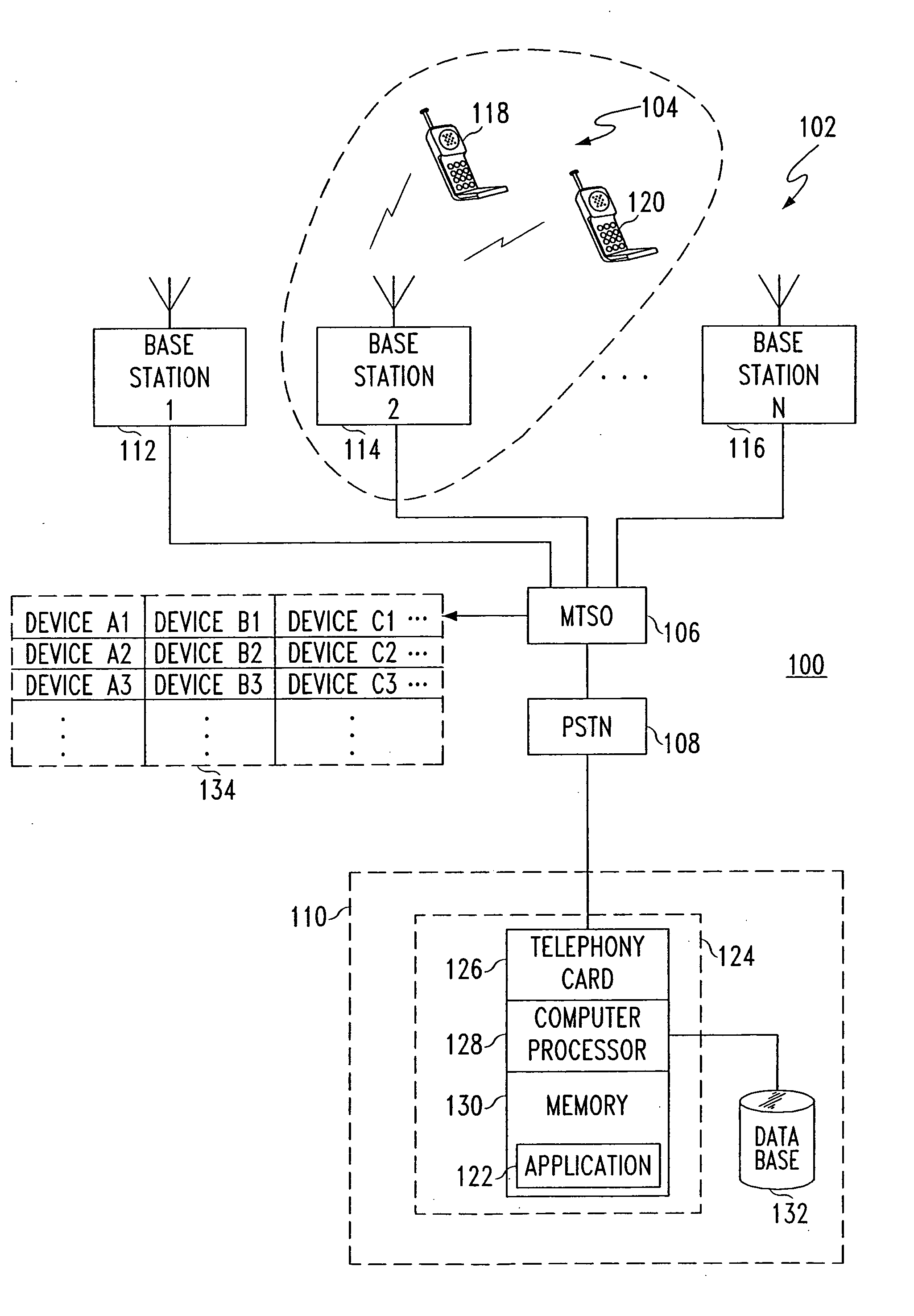
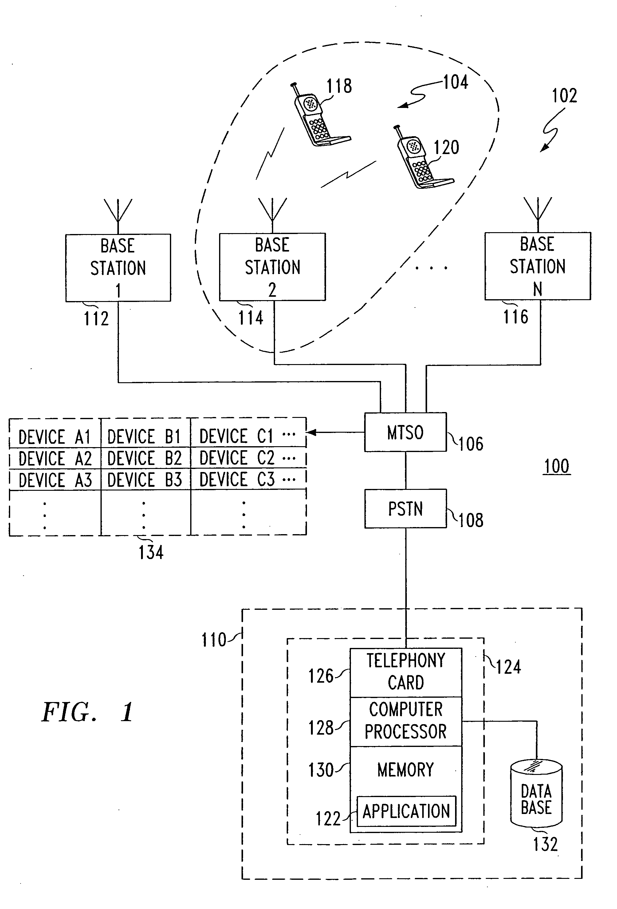
[0027]FIG. 1 is a block diagram of a telecommunication system 100. Telecommunication system 100 includes a public switched telephone network (PSTN) 108 and a wireless communication system 102. In this embodiment, wireless communication system 102 is a cellular telephone system having a plurality of mobile telephone switching offices (MTSO), such as an MTSO 106, and a plurality of base stations coupled to the MTSOs, such as base stations 112, 114, and 116 coupled to MTSO 106. A plurality of wireless telephone units 104 are served by the plurality of base stations 102 in wireless communication system 102, such as wireless telephone units 118 and 120 being served by base station 114. In making wireless connections for calls, the MTSOs operate and select from a plurality of devices 134, which is described in more detail below.

[0028] A computer test station 110 is coupled to telecommunication system 100 and is located remotely from the plurality of wireless telephone units 104. Computer...


PUM


Abstract

Several testing methods and apparatus for wireless communications, such as a cellular telephone communications, are described. One method for use in troubleshooting a problematic call in a wireless communication system by a computer test station includes the steps of receiving a telephone call from a wireless telephone unit while the wireless telephone unit is simultaneously connected in a call; receiving, during the telephone call, first information which identifies the wireless telephone unit and second information which identifies a wireless switch utilized in the call; sending, during the telephone call, a trace command having the caller ID information to an address associated with the wireless switch; and receiving, in response to sending the trace command, call trace information including information that identifies a plurality of devices of the wireless switch utilized in the call. In response, the computer test station delivers a message that includes this device information to, for example, the wireless telephone unit or a system maintenance computer for appropriate handling.

Description

BACKGROUND OF THE INVENTION [0001] 1. Field of the Invention [0002] The present invention relates generally to the field of testing methods and apparatus for wireless communications, such as cellular telephone communications. [0003] 2. Description of the Related Art [0004] Conventional testing methods for use in wireless communications, such as cellular telephone communications, employ a laptop computer connected to a wireless communication device, such as a cellular telephone. During “drive testing,” software in the laptop computer records data, such as signal strength data and channel identification data. The software may also provide some automated control of the cellular telephone, such as an automated repetitive dialing of telephone numbers for making telephone calls. The laptop computer is connected to the cellular telephone via a serial interface connection that is unique to the make and / or model of the cellular telephone. Software in the laptop computer that facilitates data...

Claims


Application Information

Patent Timeline
Patent Type & Authority Applications(United States)
IPC IPC(8): H04Q7/20
CPCH04B17/0085
Inventor LIPSIT, JAMES MASON
Owner AT&T MOBILITY II LLC
Learn More