Device for irradiation therapy with charged particles

a technology of charged particles and irradiation therapy, which is applied in the field of devices for irradiation therapy with charged particles, can solve the problems of high cost of such a proton or heavy ion therapy system, beam lines that cannot irradiate the target, and still a complex mechanical structur

Inactive Publication Date: 2006-05-18
ION BEAM APPL
View PDF11 Cites 147 Cited by
  • Summary
  • Abstract
  • Description
  • Claims
  • Application Information

AI Technical Summary

Problems solved by technology

The total weight of the rotating structure, including the magnets, may be as high as 100 T. The rotating structure may be as large as 10 m in diameter and 10 m in length, leading to an excessive cost of such a proton or heavy ion therapy system.
A number of fixed beam lines does not allow to irradiate the target from any direction.
Even though its weight is inferior to that of a rotating gantry, this is still a co

Method used


Image

  • Device for irradiation therapy with charged particles
  • Device for irradiation therapy with charged particles
  • Device for irradiation therapy with charged particles

Examples


Embodiment Construction

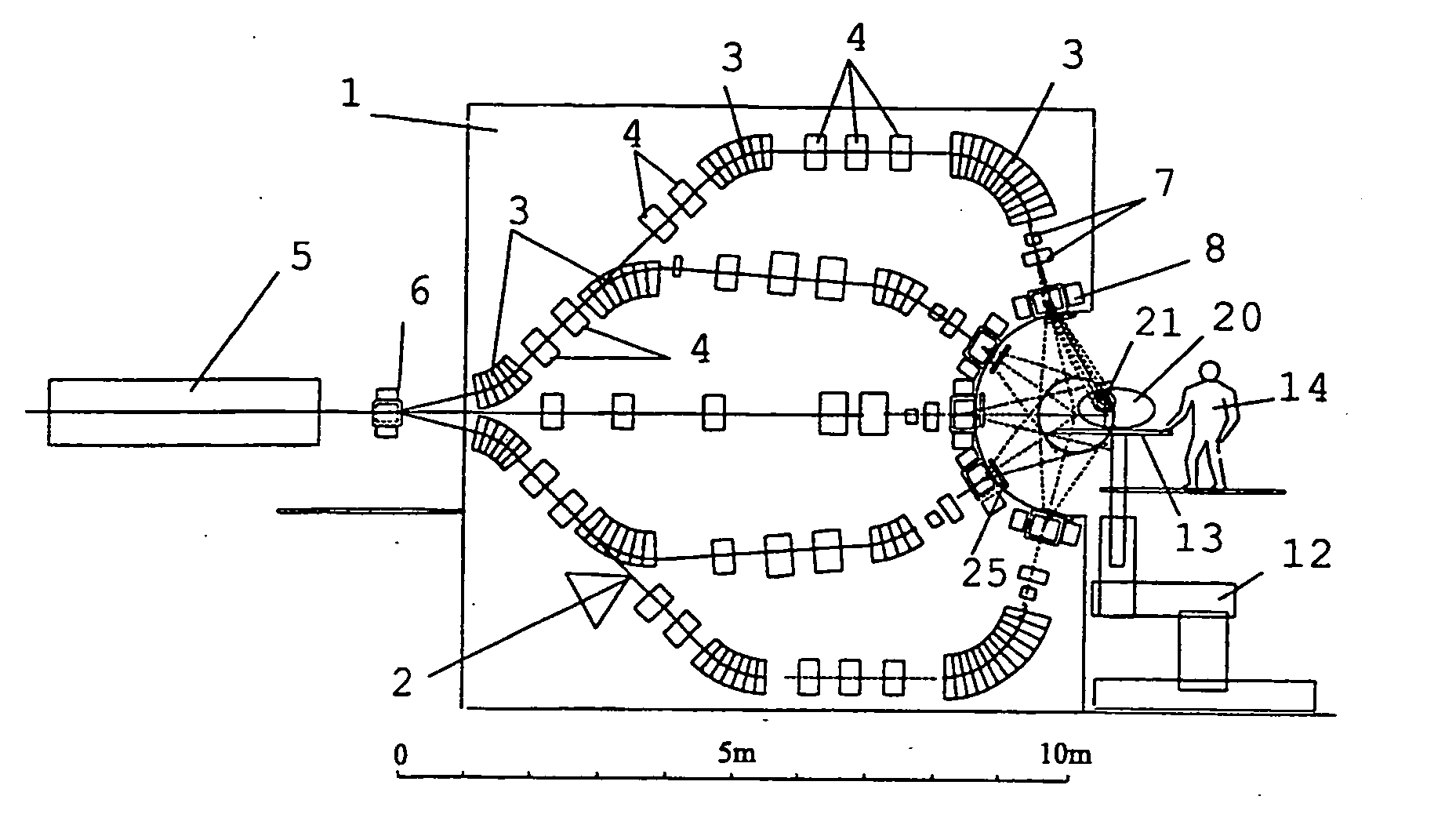
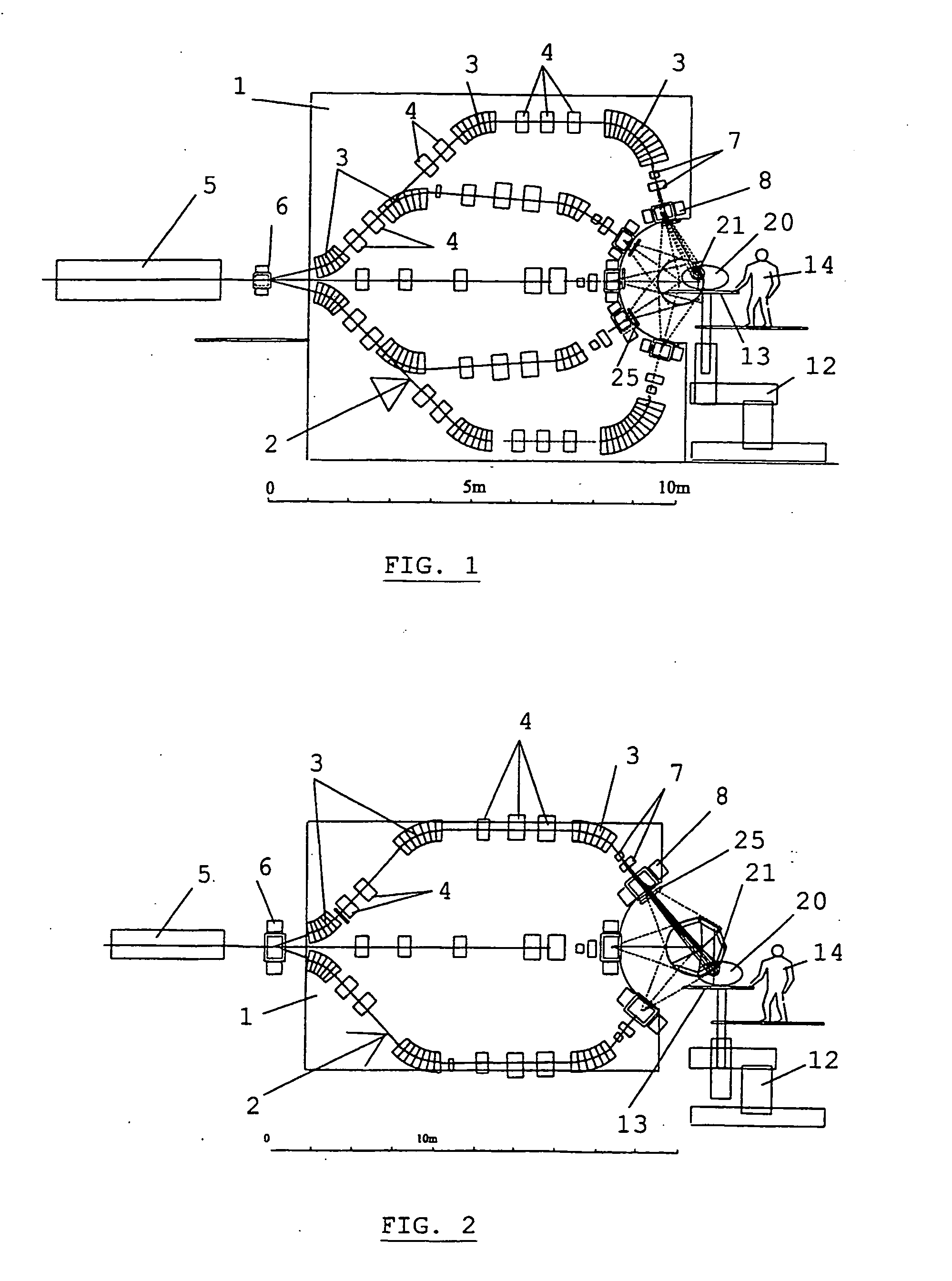
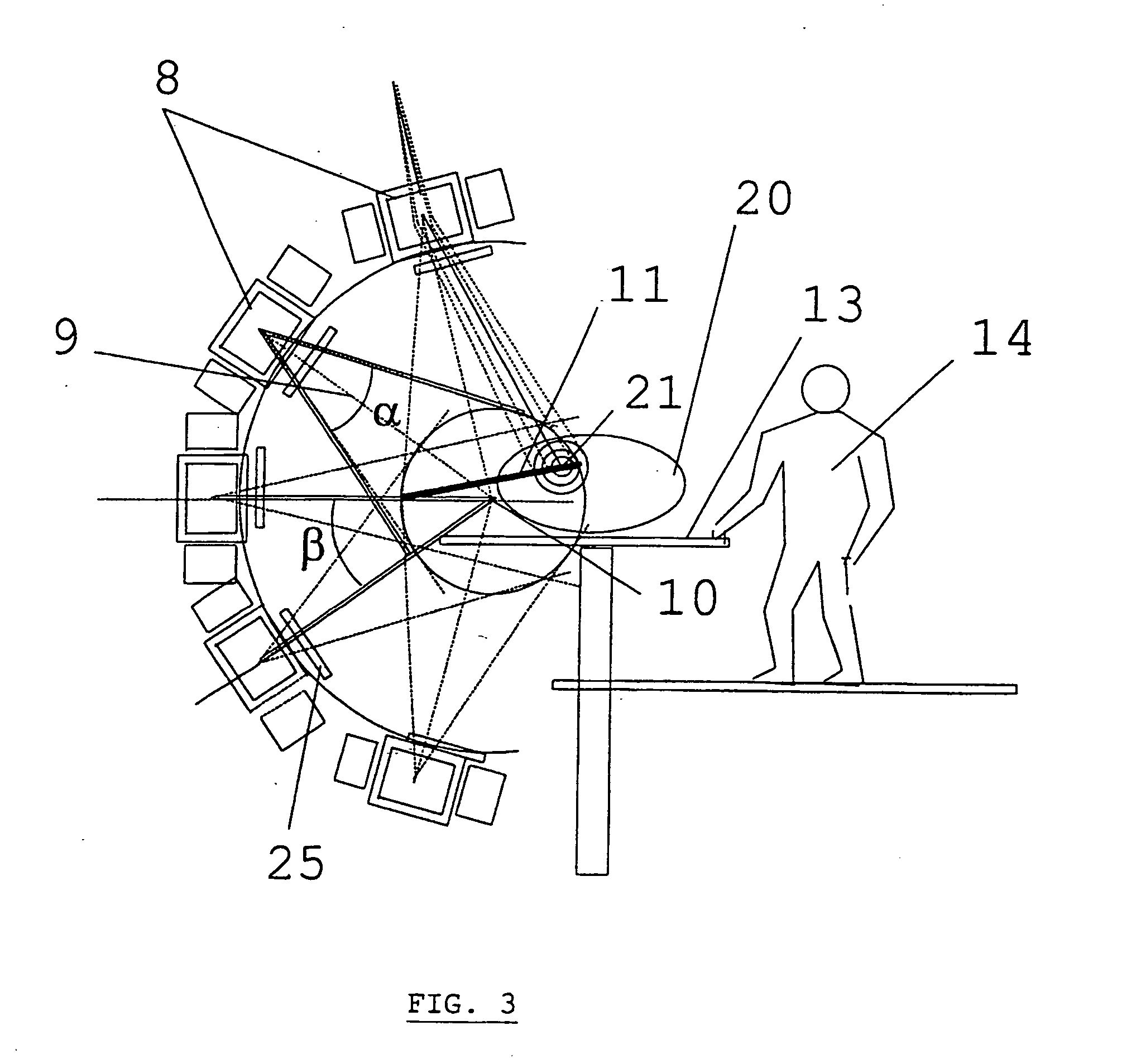
[0018] As seen in FIG. 1, the device according to the invention comprises a plurality of fixed magnetic channels 2, in a vertical plane, preferably fastened to a vertical wall 1. A channel is defined as a sequence of magnets and lenses, which force a particle beam onto a predefined path, in the plane of the vertical wall. In the case of FIG. 1, five channels are present, but this number may differ within the scope of the present invention. FIG. 2 shows a variant comprising three channels. In the figures shown, the patient 20 is in a reclining position, lying on a couch 13.

[0019] Each channel comprises a number of deflecting magnets 3 and lenses 4. The beam is produced by a common source, which is a known particle accelerator 5, for example a cyclotron, and a beam transport system. One deflecting magnet 6 is common to all channels, and provides the first deflection in the direction of one of the channels present. In the embodiment with five channels, two adjacent channels may have a...


PUM


Abstract

The present invention is related to a device for irradiating a patient with a charged particle beam, comprising a number of beam channels attached to a vertical wall, wherein a deflection magnet is present at the end of each channel. This deflection magnet is able to deflect the beam in the vertical plane over a given angle range. The couch whereon the patient is reclining is mobile in the vertical plane, so that the combined movement of the patient, and the variable deflection of the beam allow one point in the patient to be irradiated from several angles in the vertical plane.

Description

FIELD OF THE INVENTION [0001] The present invention is related to a device for directing a beam of charged particles to a target from several different angles during irradiation. A device like this is often referred to as a ‘Gantry’. STATE OF THE ART [0002] A known device for directing a charged particle beam from several different angles is a rotating gantry, such as the one described in document U.S. Pat. No. 4,917,344. This type of device comprises a large barrel or squirrel-cage structure, on which magnets are mounted for directing the beam along the axis of rotation, away from it, and back again towards the isocentre, located on the rotation axis. By combining a 2π rotation of the gantry around a horizontal rotation axis with a 2π rotation of the target around a vertical axis, one can irradiate the target from any direction, i.e. from a full sphere (4π solid angle). In order to achieve a good precision in the direction of the beam, the requirements on the mechanical structure i...

Claims


Application Information

Patent Timeline
IPC IPC(8): A61B5/05A61N5/10G21K1/093
CPCA61N5/10A61N5/1078A61N5/1081A61N5/1084A61N2005/1087
Inventor KATS, MARK
Owner ION BEAM APPL
Why Eureka
Try Eureka