

Vending machine monitoring system
- Summary
- Abstract
- Description
- Claims
- Application Information
AI Technical Summary
Benefits of technology
Problems solved by technology
Method used
Image

Examples
first embodiment
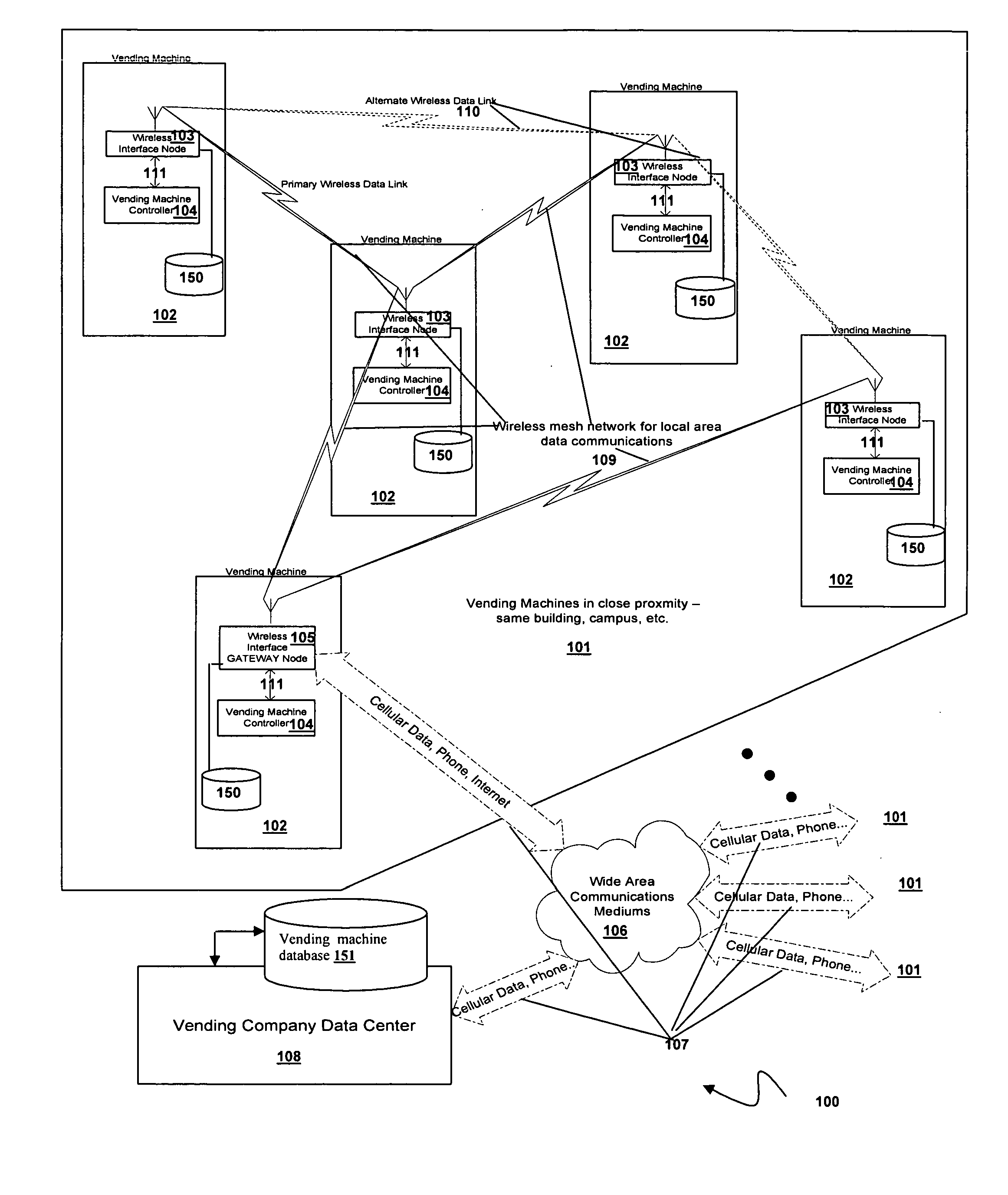
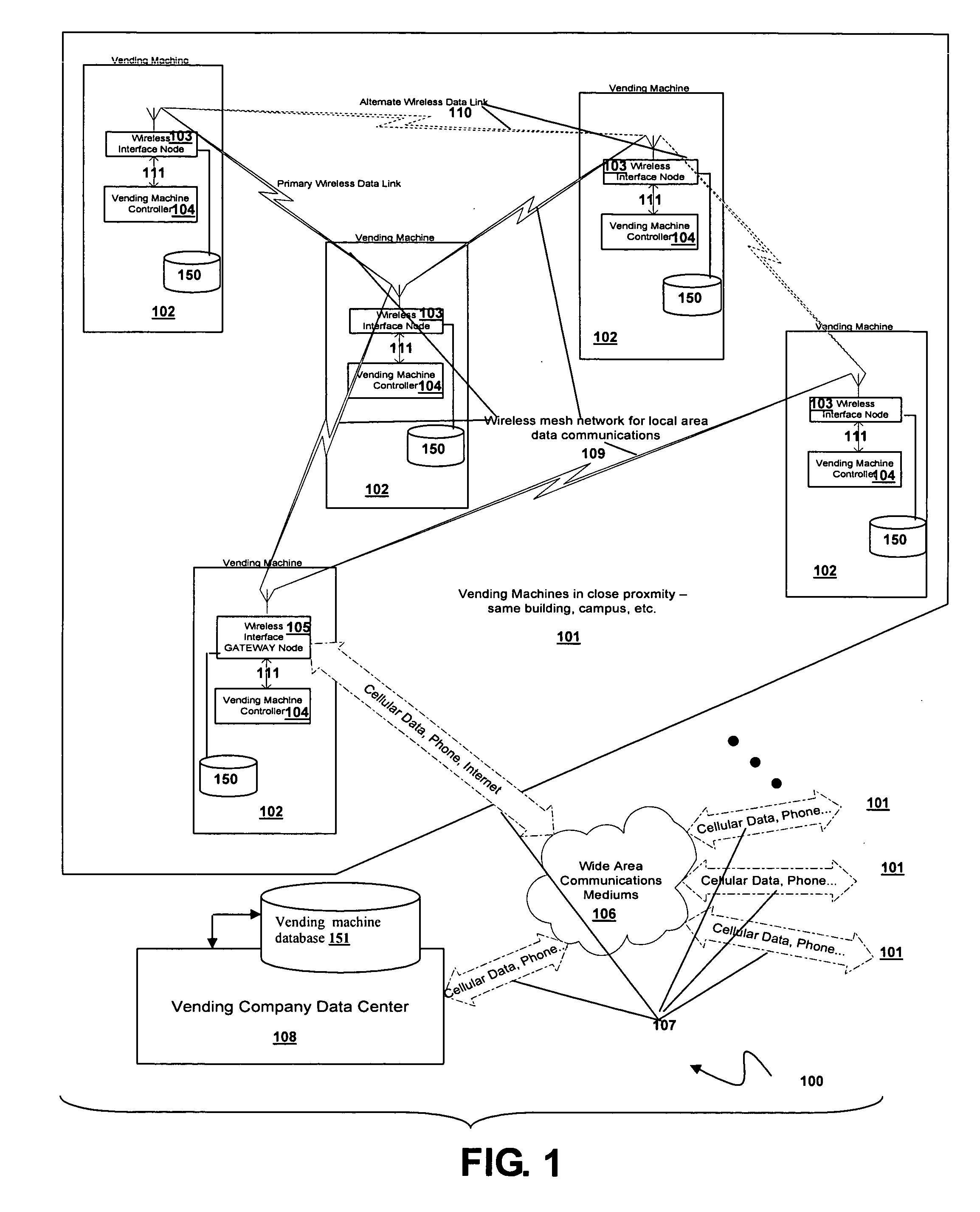
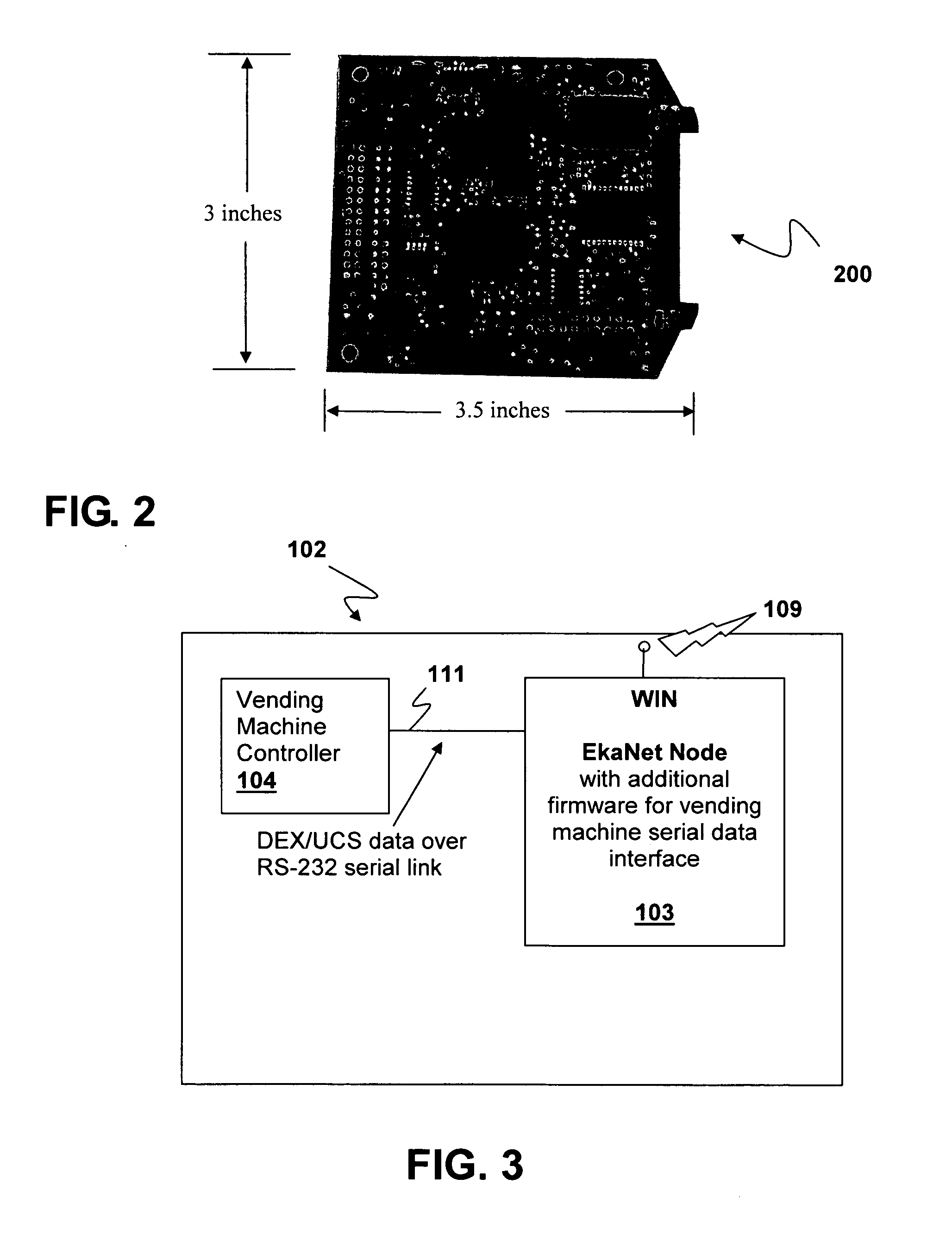
[0036]FIG. 5 illustrates a vending machine 102 employing a system 500 with a gateway node with GSM cellular connectivity via a GSM modem 114 (for example a Spider SA-GL GSM Modem) for wireless connectivity to a remote vending machine monitoring data center 113. The vending machine 102 has a WIN 105 configured as an off-the-shelf EkaNet Node with additional firmware for vending machine serial data interface according to an embodiment of the present invention. The system 500 interacts with a wireless mesh network 109. DEX / UCS data transmits over an RS-232 serial link 111 between the vending machine controller 104 and EkaNet Node 105. Compressed DEX / UCS data travels over RS-232 data link 112 to the GSM modem 114. Data travels from the GSM modem 114 to the vending company data center 113 via GSM technology. The GSM technology may be replaced by any wireless technology.
second embodiment
[0037]FIG. 6 illustrates a vending machine 102 employing a system 600 with a gateway node with telephone connectivity via a telephone modem 116 to a remote vending machine monitoring data center 115. The vending machine 102B has a WIN 105 configured as an off-the-shelf EkaNet Node with additional firmware for vending machine serial data interface according to an embodiment of the present invention. The system 600 interacts with the wireless mesh network 109. DEX / UCS data transmits over an RS-232 serial link 111 between the vending machine controller 104 and EkaNet Node 105. Compressed DEX / UCS data travels over RS-232 data link 112 to the telephone modem 116. Data travels from the telephone modem 116 to the vending company data center 115. The transmitted data from the telephone modem 116 may travel to the vending company data center either directly along the telephone line or may travel by a combination of telephone and internet. For example, the data may travel along a phone line t...
third embodiment
[0038]FIG. 7 illustrates a vending machine 102 using a serial to Ethernet converter in a gateway node for wired connectivity to a remote vending machine monitoring data center. The vending machine 102C employs a system 700 with a gateway node with Ethernet / Internet connectivity from a serial to Ethernet converter 119 to a remote vending machine monitoring data center 118. The vending machine 102C has a WIN 105 configured as an off-the-shelf EkaNet Node with additional firmware for vending machine serial data interface according to an embodiment of the present invention. The system 700 interacts with the wireless mesh network 109. DEX / UCS data transmits over an RS-232 serial link 111 between the vending machine controller 104 and EkaNet Node 105. Compressed DEX / UCS data travels over RS-232 data link 112 to the serial to Ethernet converter 119. Then data travels from the serial to Ethernet converter 119 via the Internet to the vending company data center 118.
[0039] A preferred embodim...
PUM
 Abstract
Description
Claims
Application Information