Method for discovery reply packet transmission in communication network

a communication network and packet transmission technology, applied in the field of communication systems, can solve the problems of packets beyond the storage capacity of the queue lost or dropped, and achieve the effect of reducing the drop ratio of discovery reply packets

Inactive Publication Date: 2006-05-18
SAMSUNG ELECTRO MECHANICS CO LTD
View PDF10 Cites 31 Cited by
  • Summary
  • Abstract
  • Description
  • Claims
  • Application Information

AI Technical Summary

Benefits of technology

[0018] The present invention has been provided to solve the above-mentioned and other problems and disadvantages occurring in the conventional arrangement, and an aspect of the present invention provides a method for reducing a drop ratio of a discovery reply packet, which is transmitted from a sensor nodes, at an access point (AP) in a network including a plurality of sensor nodes.
[0019] Another aspect of the present invention provides a method for rapidly receiving context information at a user by decreasing a packet drop ratio at an AP.

Problems solved by technology

The packets beyond the storage capacity of the queue are lost or dropped.

Method used


Image

  • Method for discovery reply packet transmission in communication network
  • Method for discovery reply packet transmission in communication network
  • Method for discovery reply packet transmission in communication network

Examples


first exemplary embodiment

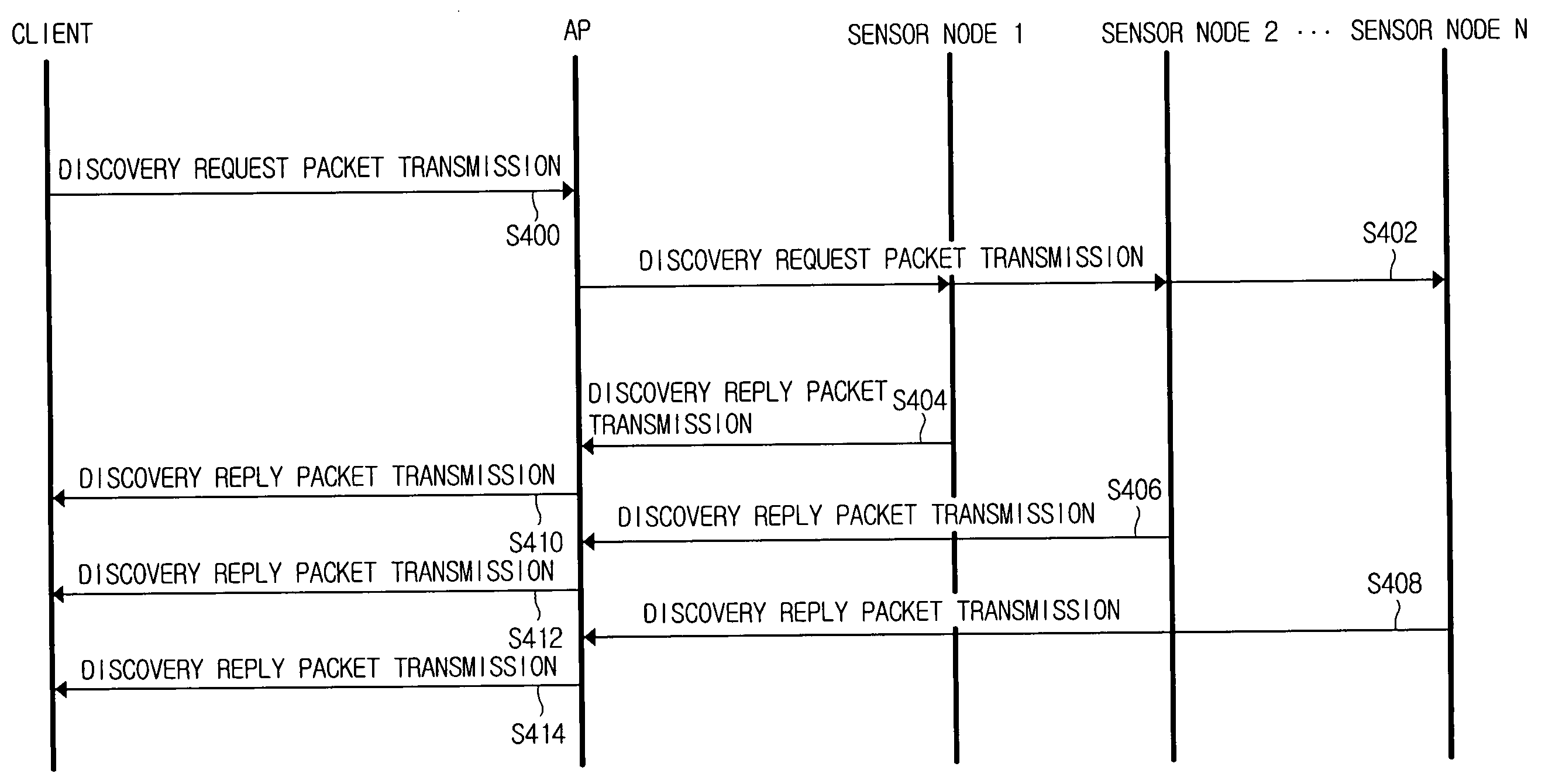
[0035]FIG. 4 illustrates a communication network according to a first embodiment of the present invention. In FIG. 4, the communication network includes a client, an access point (AP), and a sensor node 1 through a sensor node N, similarly to FIG. 2. Hereinafter, the first embodiment of the present invention is described in reference to FIG. 4. Although FIG. 4 depicts the AP, the AP can be any device capable of relaying packets between the sensor nodes and the client.

[0036] The client transmits a discovery request packet to the AP (S400). Information contained in the discovery request packet has been set forth in reference to FIG. 2. The AP forwards the received discovery request packet to neighbor sensor nodes (S402). Referring back to FIG. 2, the AP forwards the discovery request packet to the sensor node 1 through the sensor node N. As such, the AP can multicast one discovery request packet to the sensor node 1 through the sensor node N. The AP may duplicate the received discove...

second exemplary embodiment

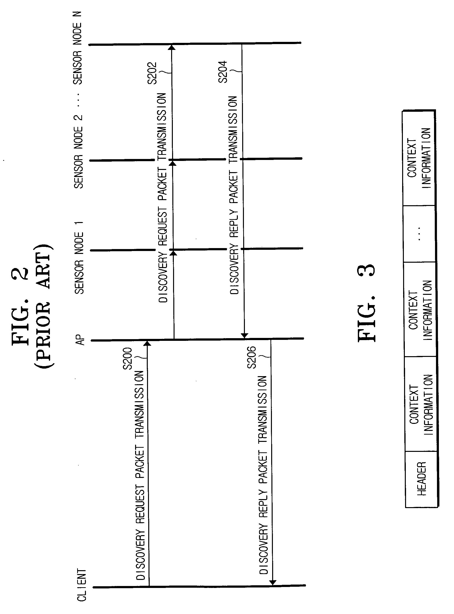
[0047] In the first embodiment of the present invention, the source node transmits one discovery reply packet without packet fragmentation. According to the second embodiment of the present invention, the source node fragments the discovery reply packet into at least two for the transmission. The number of the fragmented packets is defined as NFR in Inequality (1). It is to be understood that the number of the fragmented discovery reply packets is variable depending on the user's setting. As shown in FIG. 3, the discovery reply packet includes the header field and the plurality of the context information fields. According to the second embodiment of the present invention, the header field contains information relating to the number of the fragmented discovery reply packets. The source node appends partial information contained in the header field to the beginning of the fragmented discovery reply packets. Therefore, the client can receive the fragmented discovery reply packets and i...

third exemplary embodiment

[0055] According to the third embodiment of the present invention, the discovery reply packet is fragmented and transmitted, similarly to the second embodiment of the present invention. A difference lies in that the discovery reply packet is fragmented by a significant unit. In particular, the discovery reply packet of FIG. 3 includes the plurality of context information fields. In the third embodiment of the present invention, the discovery reply packet is fragmented by unit of the context information field. When fragmenting the discovery reply packet, the client divides the packet into a requisite part for the context information translation and an additional part. It should be appreciated that the additional part contains information additionally required for the translation of the context information.

[0056] Hereinafter, the third embodiment of the present invention is described in reference to FIG. 6.

[0057] The source node generates the discovery reply packet (S600). The sourc...


PUM


Abstract

A method for determining a transmission time of collected context information at a sensor node in a communication system that includes a client, at least one sensor node collecting context information, and an access point (AP) forwarding the context information received from the sensor node to the client. The communication system operates in a session layer of protocol layers of open systems interconnection (OSI). The sensor node calculates a transmission period in which the collected context information is transmitted, and randomly determines a transmission time at which the context information is transmitted within the calculated transmission period. Since the collected context information is transmitted at the transmission time randomly determined by the sensor node, the load on the AP can be balanced.

Description

CROSS-REFERENCE TO RELATED APPLICATIONS [0001] This application claims the benefit under 35 U.S.C. § 119 (a) from Korean Patent Application No. 2004-93906 filed on Nov. 17, 2004 in the Korean Intellectual Property Office, the entire disclosure of which is incorporated herein by reference. BACKGROUND OF THE INVENTION [0002] 1. Field of the Invention [0003] The present invention relates generally to a communication system including a plurality of sensor nodes. More specifically, the present invention relates to a method for seamlessly transmitting information collected at sensor nodes to a client. [0004] 2. Description of the Related Art [0005] Recently, the computing environment has been advancing toward a ubiquitous computing environment with the rapid prevalence of Internet and mobile networks and the convergence of wireless networks. The advent of new nodes and services has brought a trend toward compactness and intelligence. Especially, intelligent services are provided in associ...

Claims


Application Information

Patent Timeline
Patent Type & Authority Applications(United States)
IPC IPC(8): G06F17/30G06F13/00H04W4/04H04W74/04H04W74/08H04W84/12
CPCH04L67/325H04L67/12H04L69/28H04L69/329H04L67/62H04W24/10H04L12/28
Inventor YOON, HYUNG-MINKANG, WOO-SHIKPARK, KYUNG-HOHAN, TACK-DONKANG, BEOM-SEOK
Owner SAMSUNG ELECTRO MECHANICS CO LTD
Why Eureka
Try Eureka