Storage device and storage device data life cycle control method

Inactive Publication Date: 2006-05-18
HITACHI LTD
View PDF7 Cites 22 Cited by
  • Summary
  • Abstract
  • Description
  • Claims
  • Application Information

AI Technical Summary

Problems solved by technology

However, at certain points in time, there may also be cases in which there is data that is stored only in the second volume, and that is not stored in the first volume.

Method used


Image

  • Storage device and storage device data life cycle control method
  • Storage device and storage device data life cycle control method
  • Storage device and storage device data life cycle control method

Examples


first embodiment

1. First Embodiment

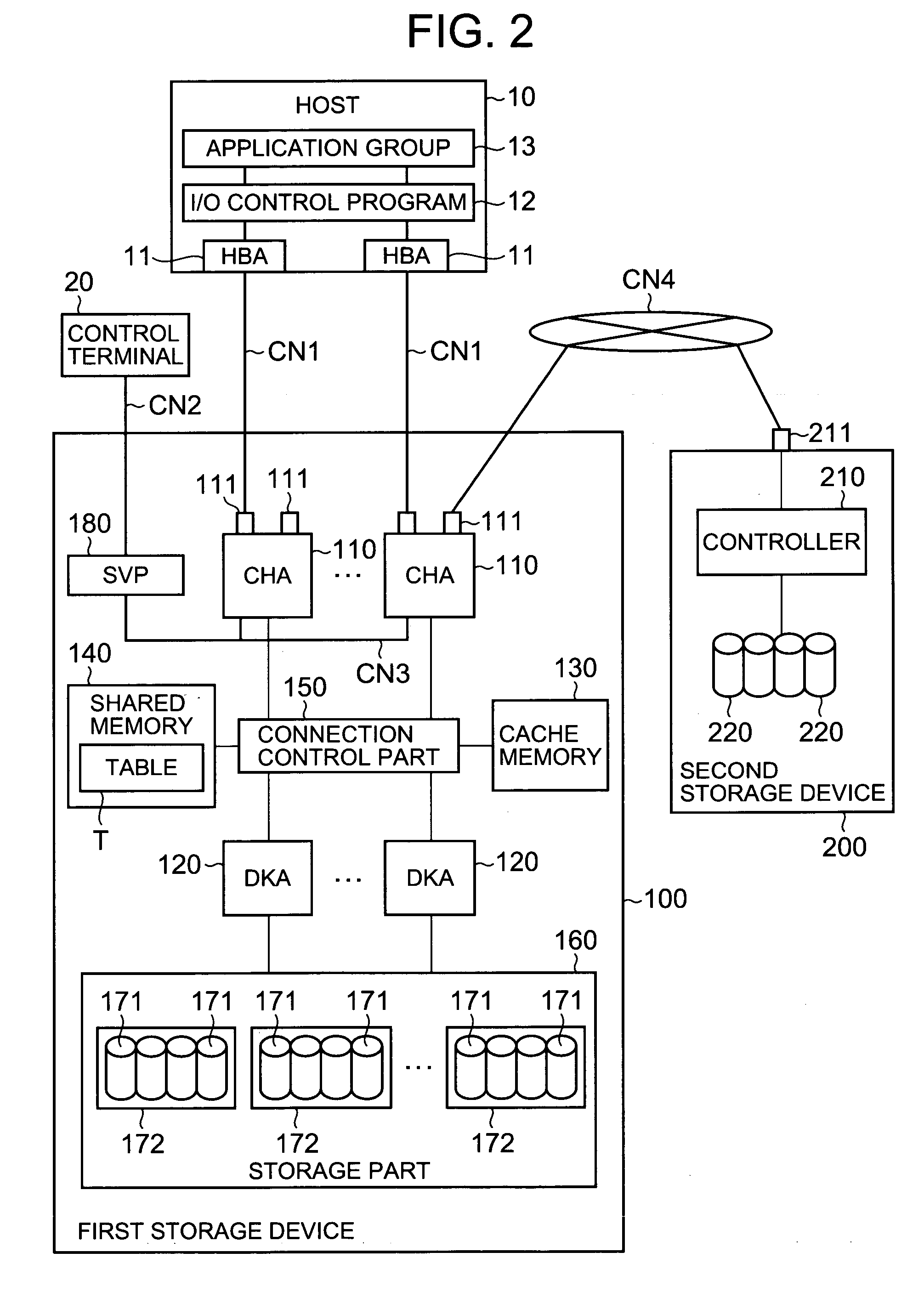
[0067]FIG. 2 is a block diagram showing an overall outline of a storage system containing a storage device 100. As will be described later, this storage system can be constructed so that this system contains one or more hosts 10, and one or a plurality of storage devices 100 and 200.

[0068] For example, hosts 10 can be roughly divided into so-called open type hosts and main frame type hosts. Examples of open type hosts include sever machines in which a common OS (operating system) such as Windows (registered trademark), UNIX (registered trademark) or the like is installed, and which access the storage device 100 via a relatively all-purpose communications protocol such as FC (fiber channel), iSCSI (internet SCSI), TCP / IP (transmission control protocol / internet protocol) or the like. Examples of main frame type hosts include main frame machines which access the storage device 100 via a communications protocol such as FICON (Fiber Connection: registered trademark), ...

second embodiment

2. Second Embodiment

[0149] A second embodiment will be described with reference to FIGS. 13 through 18. In the present embodiment, life tags are set in the host 10 in file units or directory units. Furthermore, the storage device 100 performs data redisposition (erasing of data from the high-speed volume) in accordance with life tags set by the host 10.

[0150] As is shown in the overall schematic structural diagram in FIG. 13, the host 10C in the present embodiment (like the hosts 10A and 10B in the abovementioned embodiments) comprises a life tag setting part 14 in addition to an I / O control program 12C, application group 13C and the like.

[0151] The life tag setting part 14 has a function that is used to set storage periods in stages in file units or directory units. For example, all or part of this function can be disposed inside the application group 13C. Furthermore, in the present embodiment, since life tags are set in the host 10C, a life tag setting table T2 is not stored in...

third embodiment

3. Third Embodiment

[0174] A third embodiment will be described with reference to FIG. 19. In the present embodiment, the life tag setting table T2A is expanded, so that life tags can be set even in cases where a plurality of LDEVs are associated with a single LUN.

[0175] In the life tag setting table T2A, a plurality of LDEVs and the life tags for the respective LDEVs are associated for each LUN. Thus, the present invention can be applied in cases where a single LUN (virtual volume) is constructed from a plurality of SATA volumes.


PUM


Abstract

The present invention improves the performance of a storage device by utilizing the special features of different types of volumes. The control part of the storage device constructs a virtual volume in the memory. The virtual volume is constructed by a low-speed volume and a high-speed volume, and has the same size capacity as the low-speed volume. When the application program of the host requests the updating of data, the write data is respectively written into low-speed and high-speed volumes, and a life tag that indicates the storage period is set beforehand in the virtual volume. When the storage period has elapsed, the data is erased from the high-speed volume. The data in the low-speed volume is maintained “as is”. While the data is held in the high-speed volume, access from the host is processed utilizing the data in the high-speed volume.

Description

CROSS-REFERENCE TO RELATED APPLICATIONS [0001] This application relates to and claims priority from Japanese Patent Application No. 2004-328806 filed on Nov. 12, 2004, the entire disclosure of which is incorporated herein by reference. BACKGROUND OF THE INVENTION [0002] 1. Field of the Invention [0003] The present invention relates to a storage device and a storage device data life cycle control method. [0004] 2. Description of the Related Art [0005] In storage devices, for example, storage regions based on an RAID (redundant array of independent disks) are constructed using storage devices such as hard disk drives, semiconductor memory drives or the like. For example, such physical storage regions (logical volumes) are provided to host computers (hereafter referred to as “hosts”) such as server machines or the like. Application programs operating in the hosts provide information processing services to client terminals connected to the hosts by writing data into the logical volumes ...

Claims


Application Information

Patent Timeline
Patent Type & Authority Applications(United States)
IPC IPC(8): G06F12/00
CPCG06F3/061G06F3/064G06F3/0652G06F3/0665G06F3/067
Inventor MUROTANI, AKIRAISHII, KENJI
Owner HITACHI LTD
Why Eureka
Try Eureka