Microcomputer
- Summary
- Abstract
- Description
- Claims
- Application Information
AI Technical Summary
Benefits of technology
Problems solved by technology
Method used
Image

Examples
first embodiment
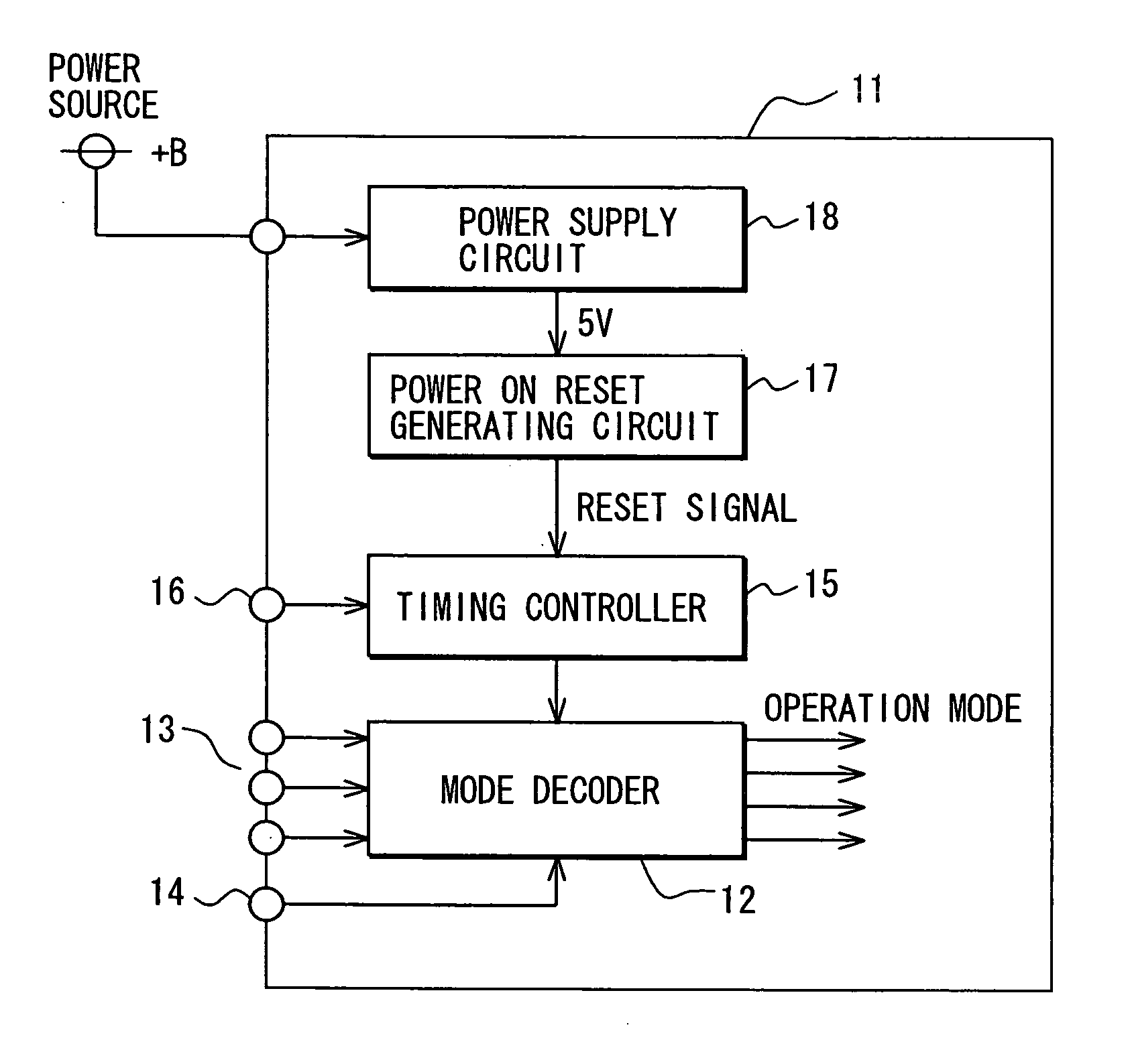
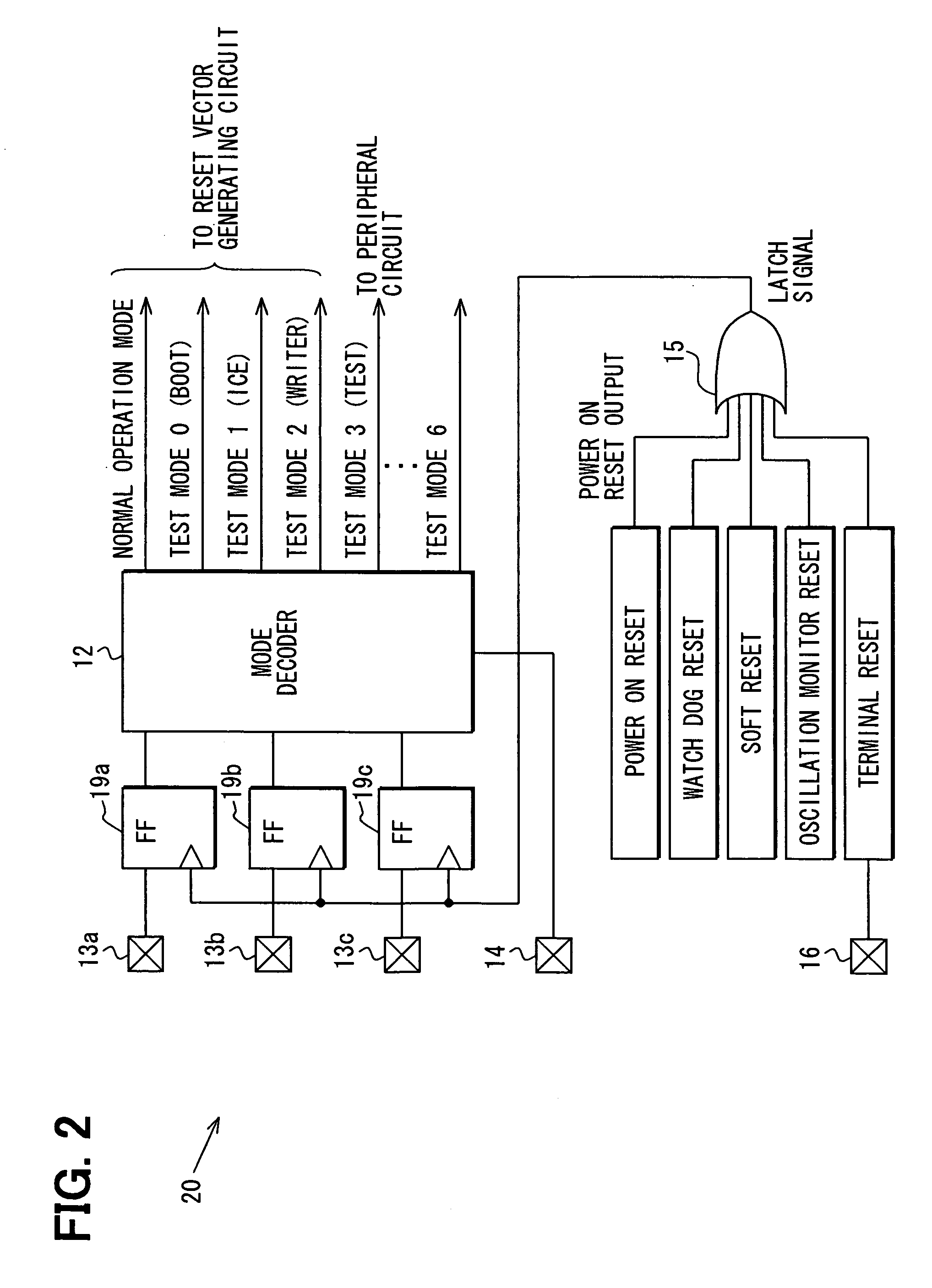
[0029] A first embodiment will be described with reference to FIGS. 1 to 4. FIG. 1 is a functional block diagram showing only a portion of the construction of a microcomputer 11. A mode decoder 12 decodes respective data levels externally set by a plurality (for example, “3”) operation mode selecting terminals 13 to output an operation mode signal of the microcomputer 11. A mode transition enable terminal 14 is a terminal for supplying an enable signal from the external for allowing the mode decoder 12 to carry out a decode operation.
[0030] A mode determining timing controller (timing signal output unit) 15 outputs a timing signal for making the mode decoder 12 execute the decode operation, and supplied as input signals with a reset signal (release signal) supplied from the external through a reset terminal 16, a power-on-reset signal (release signal) output from a power-on-reset generating circuit 17, etc. The power-on-reset generating circuit 17 receives 5V power generated on the...
second embodiment
[0052]FIG. 5 shows a second embodiment. The same elements as the first embodiment are represented by the same reference numerals, the description thereof is omitted, and only the different portion will be described. For example, a sequential comparison type AD converter (internal circuit) 22 is mounted in a microcomputer 21 of the second embodiment. The AD converter 22 has a well-known construction, and the internal construction and operation thereof will be briefly described.
[0053] The microcomputer 21 is provided with AD reference terminal (external terminal) 23(+), terminal 23(−), and a plurality of AD input terminals 24 (1 to N) as external terminals connected to the AD converter 22. The AD reference terminal 23(+) and terminal 23(−) are terminals for supplying reference voltages (+), (−) from the external of the microcomputer 21 to a DA converter 25 in the AD converter 22. When the microcomputer 21 operates at 5V, the reference terminal 23(+) is normally set to 5V by the exter...
third embodiment
[0061]FIG. 6 shows a third embodiment, and only the different portion from the first embodiment will be described.
[0062] In a microcomputer 31 according to a third embodiment, a power supply circuit 32 replacing the power supply circuit 18 is designed to generate and output 5V power source only to generate a power-on-reset signal to the power-on-reset generating circuit 17. When the microcomputer 31 is mounted on the printed board as shown in FIG. 3, an external power supply circuit (external circuit) 33 constructed at the substrate side is connected to the microcomputer 31, and the internal circuit of the microcomputer 31 is provided with operating power from the power supply circuit 33.
[0063] The power supply circuit 33 is constructed as follows. That is, the emitter of a PNP transistor 34 is connected to the power source +B through a resistor 35, and the collector thereof is connected to the 5V power source terminal 36. The emitter of an NPN transistor (current control transist...
PUM
 Abstract
Description
Claims
Application Information
 - R&D
- Intellectual Property
- Life Sciences
- Materials
- Tech Scout
- Unparalleled Data Quality
- Higher Quality Content
- 60% Fewer Hallucinations
Browse by: Latest US Patents, China's latest patents, Technical Efficacy Thesaurus, Application Domain, Technology Topic, Popular Technical Reports.
© 2025 PatSnap. All rights reserved.Legal|Privacy policy|Modern Slavery Act Transparency Statement|Sitemap|About US| Contact US: help@patsnap.com