Laundry processing apparatus

a technology for washing machines and washing machines, applied in the direction of other washing machines, washing machines with receptacles, textiles and paper, etc., can solve the problems of increased manufacturing cost of laundry washing machines, increased purchase cost of pumps, and complicated control, so as to reduce the amount of water used, increase the pumping pressure and the effect of pumping water flow

Active Publication Date: 2019-12-05
LG ELECTRONICS INC
View PDF0 Cites 1 Cited by
  • Summary
  • Abstract
  • Description
  • Claims
  • Application Information

AI Technical Summary

Benefits of technology

[0026]With the above-described solution, water can be sprayed with a strong pressure from the upper side, and the detergent dissolving and the cloth wetting can be rapidly performed and the solubility of the detergent can be remarkably increased.
[0027]In addition, even with a small amount of water, the detergent dissolving and the cloth wetting can be easily performed, thereby reducing the amount of water used.
[0028]Further, by rotating the blade at a relatively high rotation speed and rotating the pulsator at a relatively low rotation speed by using a single driving motor, there is an effect of increasing the pumping pressure and the pumping water flow, performing smooth washing, and reducing wear and rotational load of the laundry.
[0029]Further, there is an advantage that a separate driving motor is unnecessary, the change of the shaft system is unnecessary, and control is simple, while achieving the function of the present invention through a single shaft system, through a power transmission portion for transmitting a drive force from a single driving motor.
[0030]Further, by using a gear module, the torque load of the driving motor can be reduced, and the energy can be saved by driving the motor in a high efficiency area.
[0031]In addition, by allowing the pumped washing water to penetrate a filter portion, foreign matter such as lint can be easily removed.

Problems solved by technology

However, when a pump is provided separately from the driving motor, the purchase cost of the pump is additionally occurs.
Thus, the manufacturing cost of the laundry processing apparatus is increased, and the operation of the pump is further controlled.
Accordingly, there is a problem that the control becomes complicated.

Method used


Image

  • Laundry processing apparatus
  • Laundry processing apparatus
  • Laundry processing apparatus

Examples


third embodiment

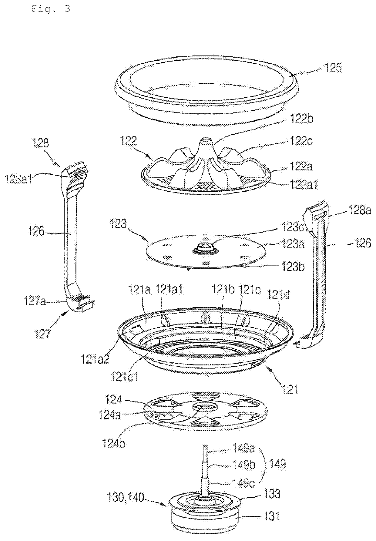
[0101]The hub 124 is fixed to the lower side surface of the base 121. The hub 124 is disposed in the central portion of the base 121. The washing water inflow holes 124a is illustrated as a fan shape, but is not limited thereto. The central portion of the hub 124 is provided with a center coupling portion 124b for coupling with a concentric shaft assembly 149, 249, and 349. The center coupling portion 124b forms a hole that penetrates in the vertical direction. The upper portion of the inner tub connecting shaft 149c, 249c, and 349c are fixed to the center coupling portion 124b. A blade connecting shaft 149b, 249b, and 349b penetrates through the hole of the center coupling portion 124b. A pulsator connecting shaft 149a, 249a, and 349a penetrates the hole of the center coupling portion 124b. Further, in the third embodiment, a jig connecting shaft 349d penetrates via the hole of the center coupling portion 124b.

[0102]The laundry processing apparatus includes the driving motor 130 d...

second embodiment

[0113]In the second embodiment, the pulsator 122 is fixed to the upper portion of a pulsator connection frame 248. The pulsator 122 is fixed to an edge portion of the pulsator connection frame 248. The pulsator 122 receives rotational force from the pulsator connection frame 248.

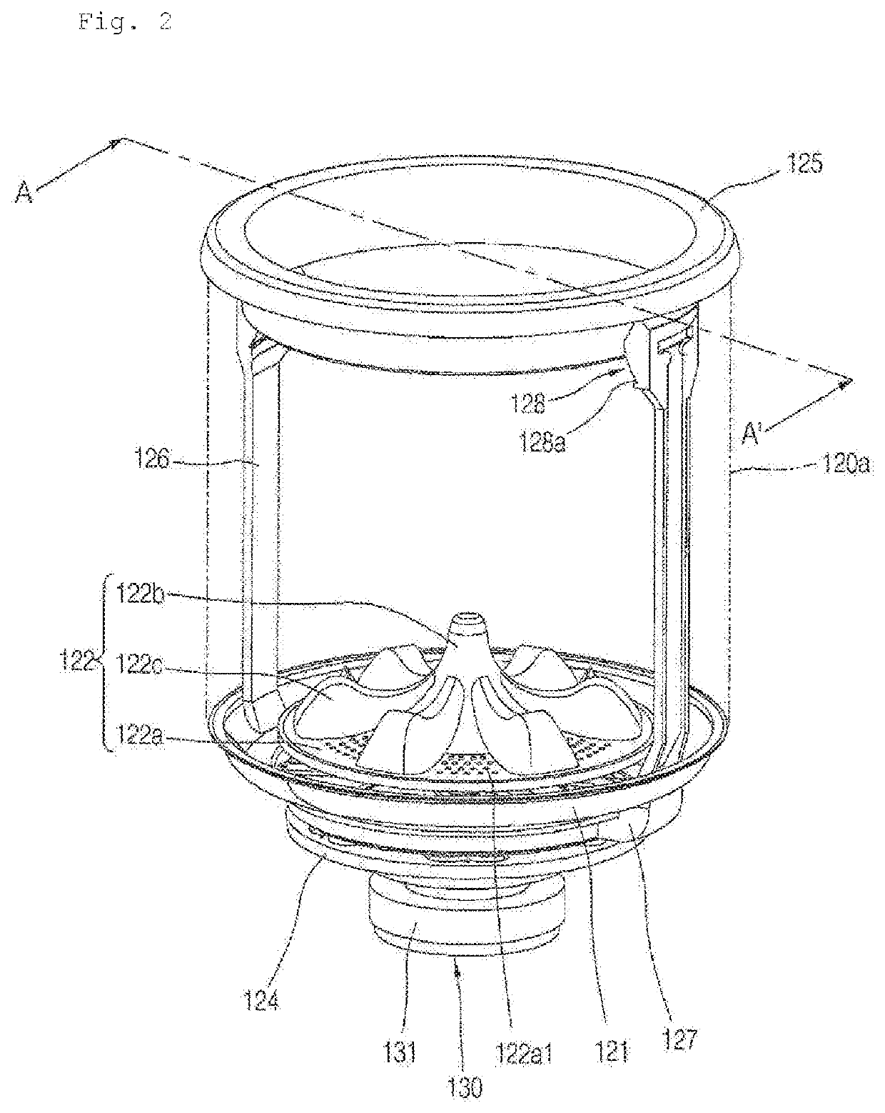
[0114]The pulsator 122 includes a rotation plate 122a forming a circular plate and a plurality of protrusions 122c protruding upward from the upper side surface of the rotation plate 122a. The pulsator 122 includes a central protrusion 122b protruding upward from the central portion of the rotation plate 122a.

[0115]The plurality of protrusions 122c are formed to extend in the centrifugal direction from the central protrusion 122b. One end of the protrusion 122c is connected to the central protrusion 122b and the other end of the protrusion 122c is extended toward the outer circumference of the rotation plate 122a. The plurality of protrusions 122c are disposed apart from each other along the circumferential...

first embodiment

[0130]Hereinafter, the power transmission portion 140 will be described in more detail with reference to FIGS. 6 to 8.

[0131]The laundry processing apparatus includes a power transmission portion 140 that transmits the rotational force of the driving motor 130 to the pulsator 122 and the blade 123, respectively. The power transmission portion 140 transmits the pulsator 122 and the blade 123 to rotate the rotational force of the driving motor 130, when only the washing shaft 132a rotates while the dewatering shaft 132b does not rotate by the clutch 137. The power transmission portion 140 transmits the rotational force of the driving motor 130 to the inner tub 120 when the dewatering shaft 132b is rotated integrally with the washing shaft 132a by the clutch 137.

[0132]The power transmission portion 140 includes a gear module 142, 143, 144, and 145 for transmitting rotational force of the washing shaft 132a to the concentric shaft assembly 149. The power transmission portion 140 include...


PUM


Abstract

A laundry processing apparatus according to the present invention includes: an outer tub which accommodates washing water therein; an inner tub which is disposed inside the outer tub and contains laundry therein; a pulsator which is provided in a lower portion of the inner tub; a blade which is provided below the pulsator; a driving motor which is disposed outside the outer tub and rotates a washing shaft; a pulsator connecting shaft which rotates the pulsator, and is disposed to penetrate a lower side surface of the outer tub; a blade connecting shaft which rotates the blade, and is disposed to penetrate the lower side surface of the outer tub; and a gear module which is disposed outside the outer tub, and transmits a rotational force of the washing shaft to the pulsator connecting shaft and the blade connecting shaft respectively.

Description

CROSS-REFERENCE TO RELATED APPLICATIONS[0001]This application is a U.S. National Phase entry under 35 U.S.C. § 371 from PCT International Application No. PCT / KR2017 / 015731, filed Dec. 29, 2017, which claims priority to Korean Application Nos. 10-2016-0182208, 10-2016-0182209, and 10-2016-0182210 all filed Dec. 29, 2016, the contents of all of which are incorporated herein by reference in their entireties.TECHNICAL FIELD[0002]The present invention relates to a laundry processing apparatus for circulating washing water by pumping the washing water to an upper portion of a washing tub using a centrifugal force.BACKGROUND ART[0003]Generally, a top loading laundry processing apparatus refers to a laundry processing apparatus for loading and unloading laundry over a washing tub. The most common form of top loading laundry processing apparatus is a pulsator type laundry processing apparatus.[0004]The pulsator-type laundry processing apparatus washes laundry by using a washing water flow ge...

Claims


Application Information

Patent Timeline
Patent Type & Authority Applications(United States)
IPC IPC(8): D06F37/14D06F37/20D06F39/08D06F37/40
CPCD06F37/14D06F37/40D06F37/206D06F39/083D06F17/10D06F17/08D06F39/08D06F37/24
Inventor YU, INSIKKIM, DONGCHEOLKIM, YOUNGJONG
Owner LG ELECTRONICS INC
Why Eureka
Try Eureka