Valve stem installation system and method of installing the valve stem

a technology of valve stems and mounting brackets, which is applied in the direction of manufacturing tools, transportation and packaging, and other domestic objects, can solve the problems of prior art systems, manual operations are subject to processing errors, and high labor costs, and achieve high degree of accuracy and precision, increase the speed and accuracy of mating, and high speed

Active Publication Date: 2006-05-25
DURR SYST INC
View PDF53 Cites 7 Cited by
  • Summary
  • Abstract
  • Description
  • Claims
  • Application Information

AI Technical Summary

Benefits of technology

[0012] A sensor is connected to the robotic manipulator and is adaptable for visually identifying the target section and transmitting the general location of the aperture within the target section via a second signal. The controller integrates the first signal and the second signal through comparative software to generate a target signal. The target signal is transmitted to the robotic manipulator for adjusting movement of the robotic manipulator relative the target section thereby increasing the speed and accuracy of mating one of the TPM and the valve stem into the aperture in response to the target signal. The subject invention includes a method of engaging the valve stem and the TPM with the wheel rim having the aperture formed therein.
[0013] Accordingly, a valve stem installation system of the present invention is new, efficient, and provides for an effective way for selectively mounting the valve stems of various configurations into the respective wheel rim desirable to develop a new design of the valve stem installation system adaptable for mating of at least two different valve stems into the wheel rim with high degree of accuracy and precision and at a high speed thereby eliminating the need of an extra unit, reduce space in manufacturing environment, and improving cost and efficiency of manufacturing process.

Problems solved by technology

Such manual processes are expensive because of the labor and time involved.
In addition, operations performed manually are subject to a processing error.
This prior art systems diminish assembly time and flexibility of assembling environment.
These systems also performs numerous redundant operations, such as moving the wheel rim to different mounting stations which does not reduce time for assembly of the wheel rims and does not offer the flexibility needed in the modern manufacturing environment.
Although the prior art valve stem installation systems are widely used in the automotive industry, these prior art designs have proven to be extremely complicated, and therefore non practicable, or have been inflexible in a manufacturing environment, particularly when a variety of valve stems are mated to a variety of the wheel rims.

Method used


Image

  • Valve stem installation system and method of installing the valve stem
  • Valve stem installation system and method of installing the valve stem
  • Valve stem installation system and method of installing the valve stem

Examples


Embodiment Construction

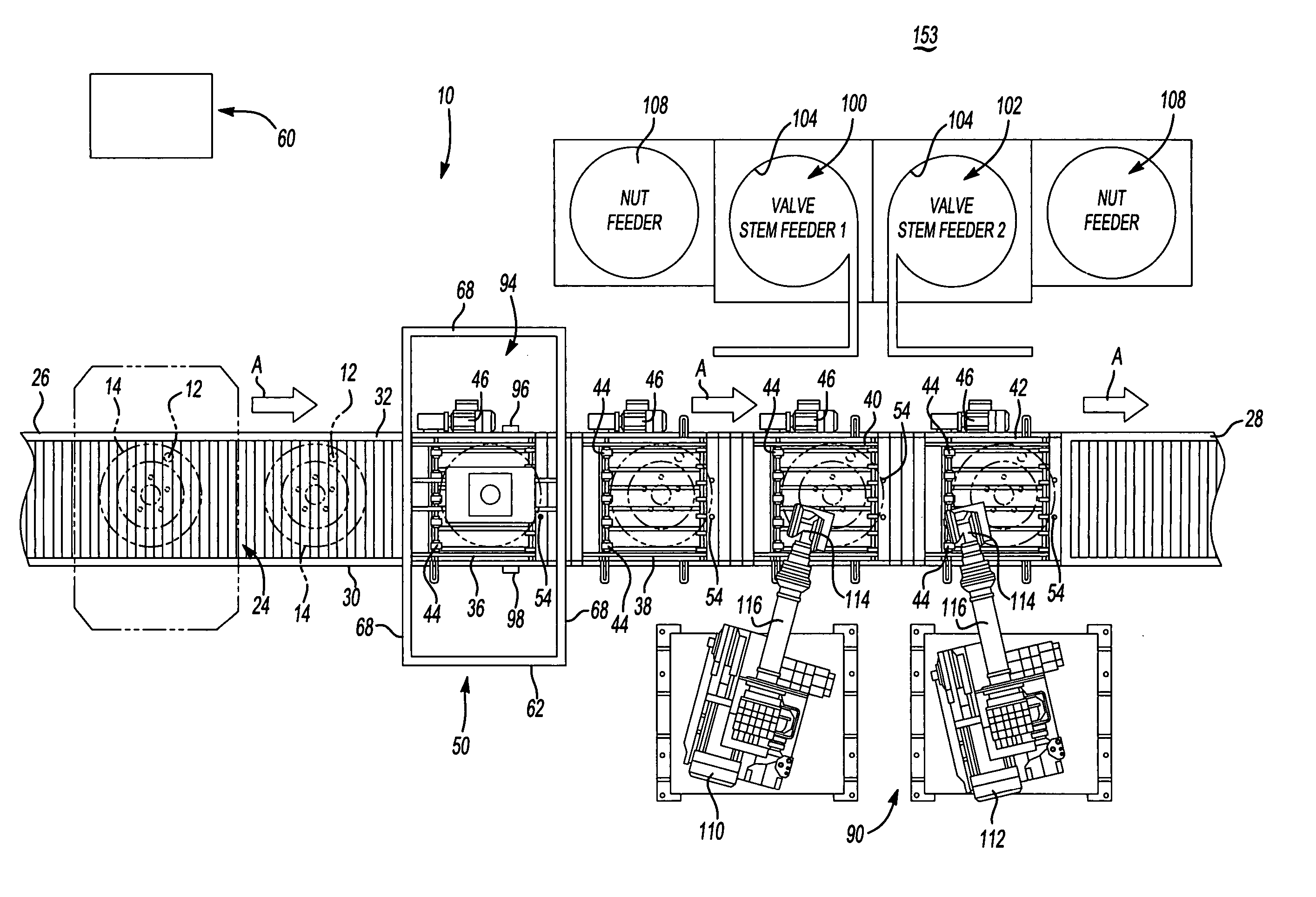
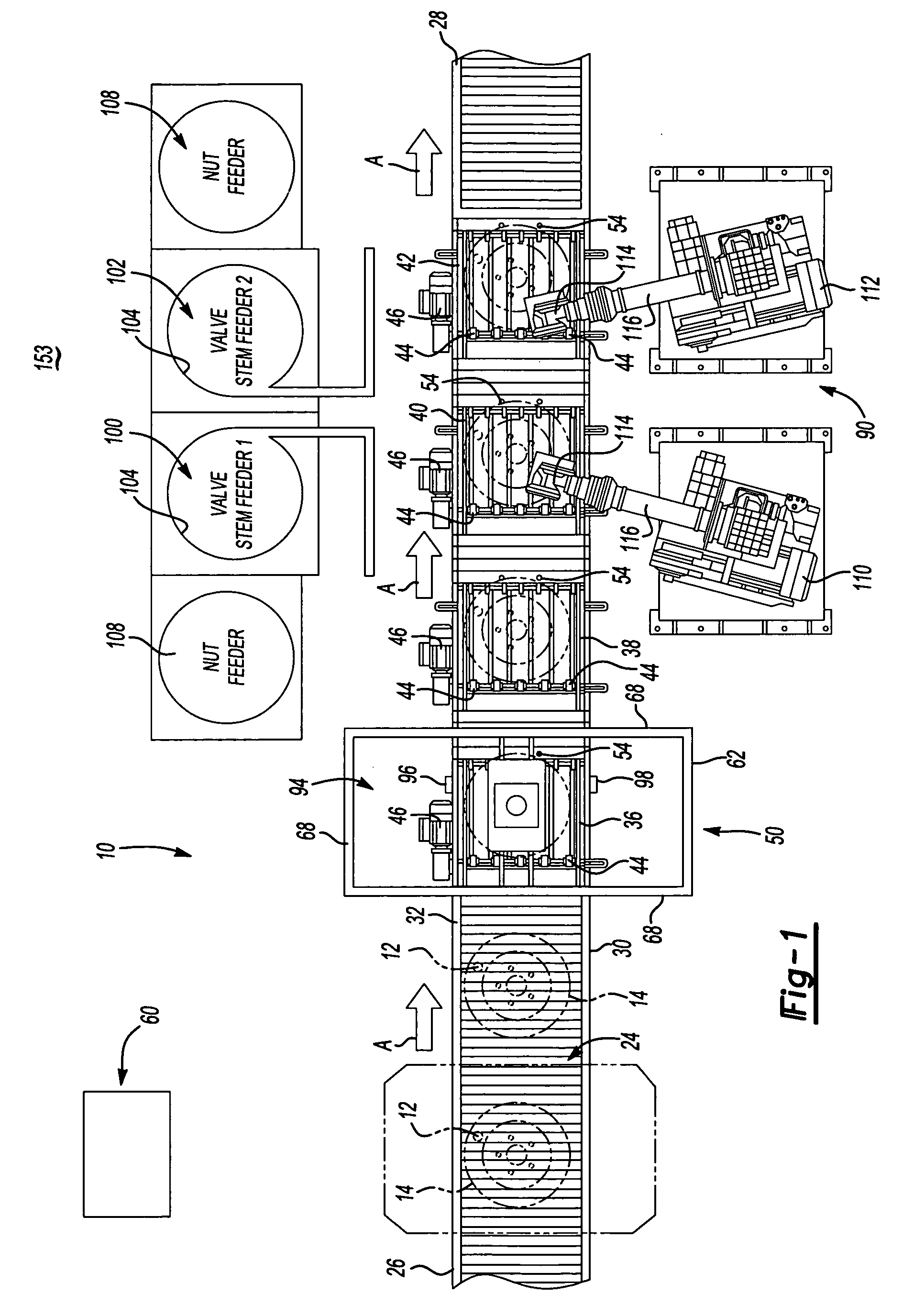
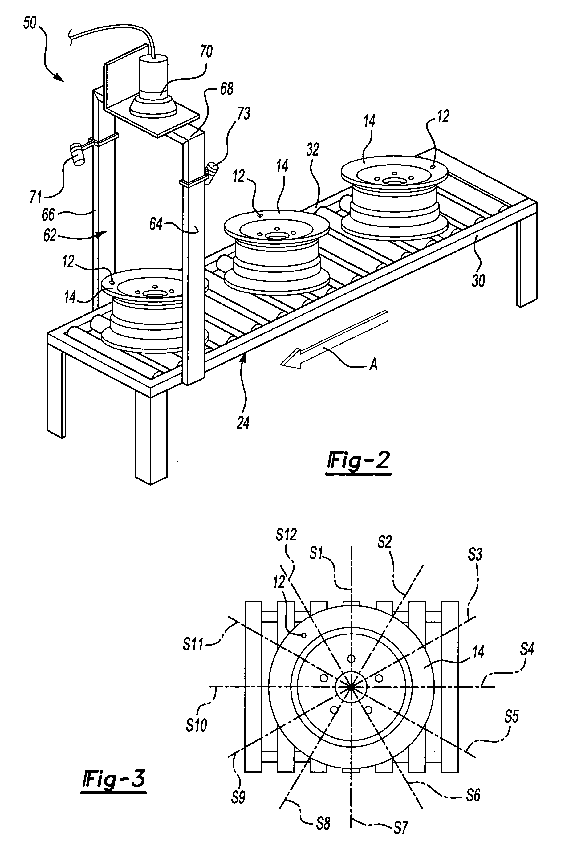
[0023] Referring to FIGS. 1 and 2, a valve stem installation system (the system) is generally shown at 10. The system 10 is adaptable to insert an individual valve stem chosen from among a plurality of differently configured valve stems into an aperture 12 defined in a wheel rim 14. These valve stems include and are not limited to a standard rubber valve stem 16 (the valve stem) and a tire pressure monitoring device type of a valve stem 18 (the TPM), both known to those skilled in the art. Any of the aforementioned valve stems is inserted in the aperture 12 as the wheel rim 14 is moved along an assembly path, generally indicated by an arrow A. The TPM 18, for example, includes a pressure sensor for monitoring the pressure in a tire mounted to the wheel rim 14 and transmits a signal corresponding to the sensed pressure. The TPM 18 is affixed to the wheel rim 14 by a nut (not shown) disposed upon an opposite side of the wheel rim 14 from the pressure sensor. The system 10 is adaptable...


PUM

PropertyMeasurementUnit
speedaaaaaaaaaa
sizesaaaaaaaaaa
sizeaaaaaaaaaa

Abstract

A valve stem installation system (10) includes a conveyor (24) for moving wheel (14). A controller (60) is adaptable for segmenting the wheel (14) into a plurality of sections (S1-S11). A detector (70) identifies and signals a general location of the aperture (12) to the controller (60) to identify a target section (S11) transmitted to the controller (60) by a first signal. A robotic manipulator (110, 112) is operably connected to the controller (60) and adaptable for inserting the valve stem into the aperture (12). A sensor (153) is connected to the robotic manipulator (110, 112) and is adaptable for visually identifying the target section (S11) and transmitting the general location of the aperture (12) within the target section by a second signal. The controller (60) generates a target signal transmitted to the robotic manipulator (110, 112) to increase the speed and accuracy of mating the valve stem into the aperture (12) in response to the target signal.

Description

RELATED APPLICATIONS [0001] This is a continuation in part application that claims the benefit of the non provisional patent application Ser. No. 11 / 095,153 for a VALVE STEM INSTALLATION SYSTEM AND METHOD OF INSTALLING VALVE STEM, filed on Mar. 31, 2005 and the benefit of the continuation in part application Ser. No. 10 / 846,823 for a VALVE STEM INSTALLATION ASSEMBLY USING RADIAL ZONE IDENTIFICATION SYSTEM, filed on May 14, 2004 and the benefit of the provisional patent application Ser. No. 60 / 606,964 for a TPM VALVE STEM INSTALLATION TOOL, filed on Sep. 3, 2004.BACKGROUND OF THE INVENTION [0002] 1. Field of the Invention [0003] The subject invention relates to a wheel and tire assembly for an automotive vehicle, and more particularly to an apparatus and method for mounting a valve stem into a wheel rim. [0004] 2. Description of the Prior Art [0005] In the assembly of automotive wheel rims and tires, the tire is mounted onto the wheel rim and then inflated. Prior to mounting the tire...

Claims


Application Information

Patent Timeline
Patent Type & Authority Applications(United States)
IPC IPC(8): B23Q17/00B23P19/00
CPCB23P19/04Y10T29/49778Y10T29/49769Y10T29/53087Y10T29/49412Y10T29/4978Y10T29/53591Y10T29/53448Y10T29/53061
Inventor MONDRUSOV, EUGENE M.GIACONA, BENHOY, BRIANPELLERIN, DAN
Owner DURR SYST INC
Why Eureka
Try Eureka