Flexible mandrel for highly contoured composite stringer

Inactive Publication Date: 2006-05-25
THE BOEING CO
View PDF4 Cites 50 Cited by
  • Summary
  • Abstract
  • Description
  • Claims
  • Application Information

AI Technical Summary

Benefits of technology

[0007] It is therefore an object to the present invention to provide an aircraft stringer lay-up assembly and method with improved flexibility to generate complex shapes, conto

Problems solved by technology

Aircraft components such as stringers have become complex in design and shape due to developing aircraft designs.
Present aircraft designs, however, can require complex contours and twists which can be difficult to implement with existing mandrel technology.
It is difficult, however, to configure these metal mandrel assemblies into the d

Method used


Image

  • Flexible mandrel for highly contoured composite stringer
  • Flexible mandrel for highly contoured composite stringer
  • Flexible mandrel for highly contoured composite stringer

Examples


Example

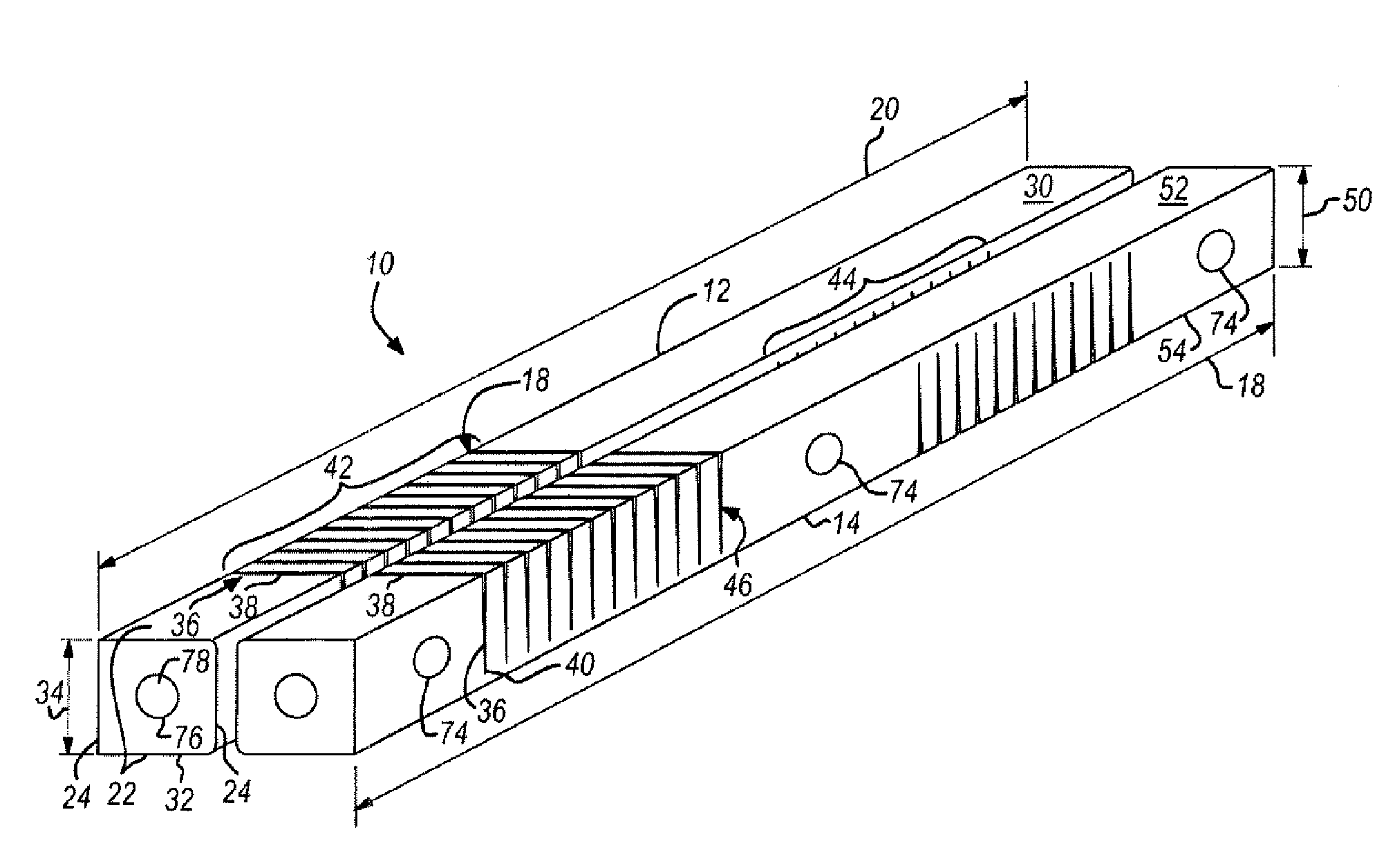
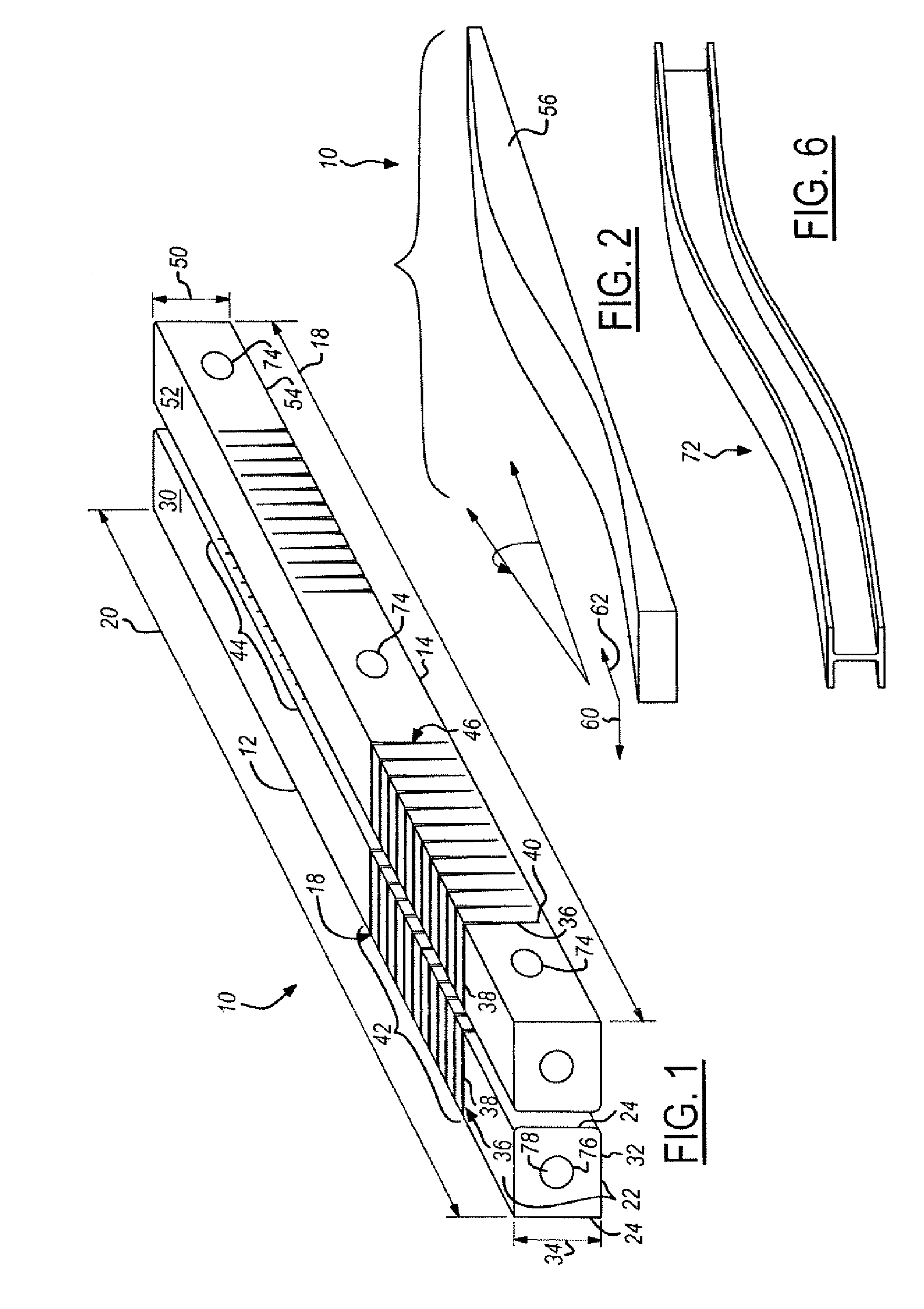
[0016] Referring now to FIG. 1, which is an illustration of an aircraft stringer lay-up assembly 10 in accordance with the present invention. The aircraft stringer lay-up assembly 10 includes a first mandrel element 12 and a second mandrel element 14. The mandrel elements 12, 14 are preferably elongated metal beams as illustrated. Traditional metal mandrel configurations suffer from an inability to conform to the complex arrangements necessary for modern stringer lay-up requirements. The present invention, however, provides a unique approach by constructing the first mandrel element 12 from a first bar assembly 16 having a plurality of rigidity reducing first elements 18 formed along its first mandrel length 20. Although a variety of rigidity reducing element 18 are contemplated, one embodiment contemplates the use of slots.

[0017] The first mandrel element 12 includes two mandrel vertical surfaces 22, two mandrel side surfaces 24, a right mandrel end surface 26 and a left mandrel e...


PUM

PropertyMeasurementUnit
Lengthaaaaaaaaaa
Lengthaaaaaaaaaa
Flexibilityaaaaaaaaaa

Abstract

An aircraft stringer lay-up assembly is provided comprising a contoured curing block and a first mandrel element positioned thereon. The first mandrel assembly includes a first bar assembly having a plurality of rigidity reducing first slots formed along a first mandrel length. The plurality of rigidity reducing first slots protruding partially through a first mandrel depth of the first mandrel element to allow the first bar assembly to conform to the contoured curing block. A composite ply assembly is laid up onto the first mandrel element and cured while conformed to said contoured curing block such that a contoured composite stringer element is generated.

Description

DESCRIPTION [0001] 1. Technical Field [0002] The present invention relates generally to an aircraft composite stringer mandrel and more particularly to a flexible mandrel for the use with an aircraft stringer lay-up assembly to produce a contoured composite stringer element. [0003] 2. Background of the Invention [0004] Aircraft components such as stringers have become complex in design and shape due to developing aircraft designs. The complexity of shape in combination with a need for decreased weight / strength ratios requires the use of alternate construction technologies. For this reason, aircraft designers have turned to the use of composite ply assemblies for the manufacture of aircraft stringers. In these manufacturing scenarios, a material ply impregnated with epoxy or similar substance is layed-up onto a mandrel shaped to generated the complex shape. The composite ply assembly is then cured to generate a composite component with the desired complex shape. [0005] Present aircra...

Claims


Application Information

Patent Timeline
IPC IPC(8): B32B37/00
CPCB29C70/345Y02T50/433B29L2031/3085B29C70/446Y02T50/40
Inventor PHAM, DOAN D.TOLLAN, MARK
Owner THE BOEING CO
Why Eureka
Try Eureka