Device for determining the overall mass of a vehicle

Inactive Publication Date: 2006-05-25
ROBERT BOSCH GMBH
13 Cites 33 Cited by

AI-Extracted Technical Summary

Problems solved by technology

A disadvantage of the design approached described in German Published Patent Application.
No. 44 09 711 is that the loa...

Benefits of technology

[0007] Furthermore, it is advantageous to have the distributed weight sensors located in the seats and on a cargo surface, for example the floor of the trunk or the roof rack. In this way, it is possible to determine the total mass and also the center of mass with very high accuracy.
[0008] It is also advantageous to link this mass value with a relative velocity of an object that is determin...

Abstract

An apparatus for determining the total mass of a vehicle, the apparatus being characterized by the fact that it has stored the curb mass of the vehicle and is connected to distributed weight sensors in the vehicle in order to determine the loaded mass in the vehicle. This includes occupants and luggage or other objects being transported. The total mass is determined by addition, and the kinetic energy is able to be calculated using, when necessary, the mass and a relative velocity between the vehicle and another object. In particular, the apparatus according to the invention allows a center of mass to be determined.

Application Domain

Technology Topic

Relative velocityEngineering +2

Image

  • Device for determining the overall mass of a vehicle
  • Device for determining the overall mass of a vehicle
  • Device for determining the overall mass of a vehicle

Examples

  • Experimental program(1)

Example

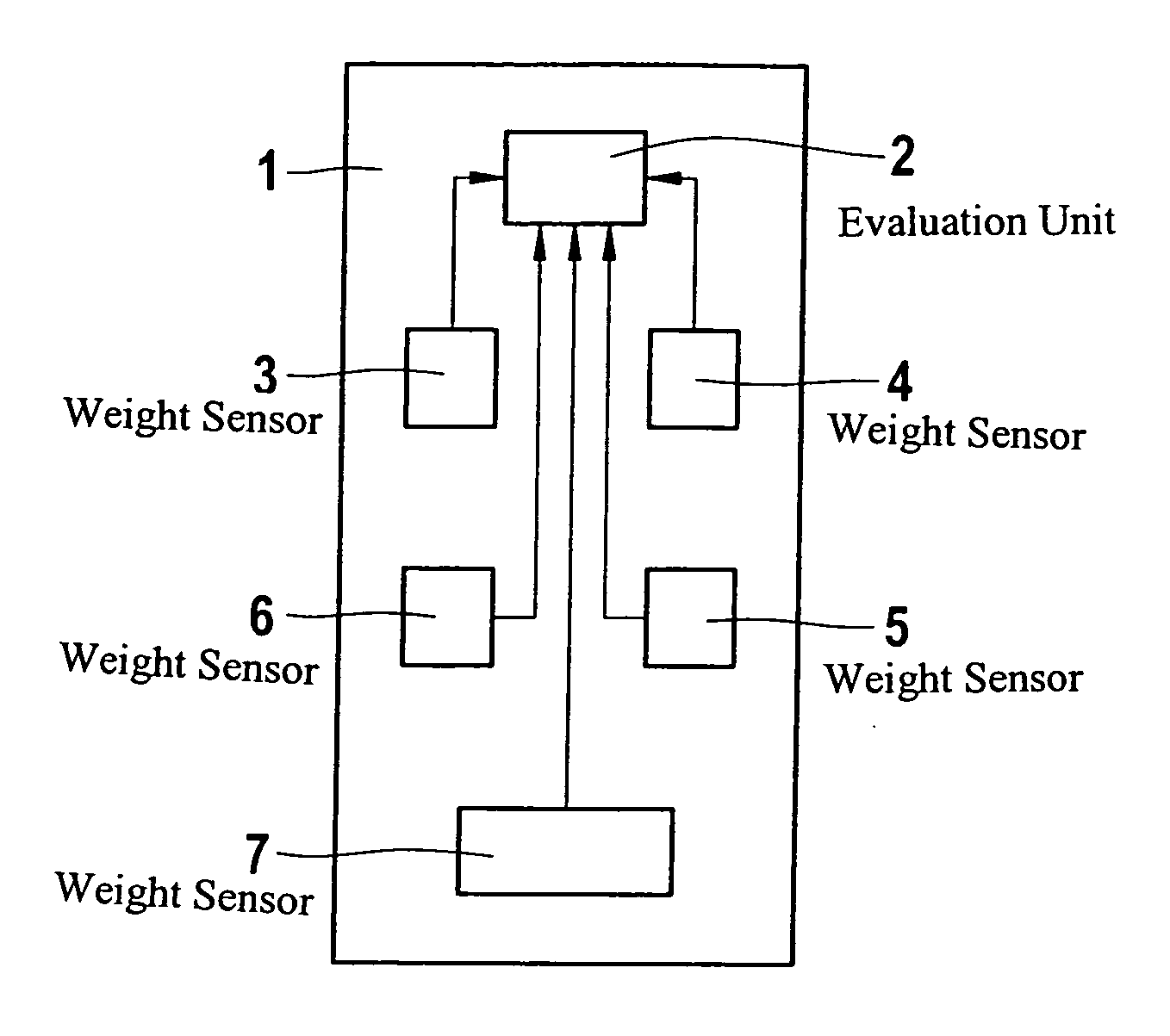
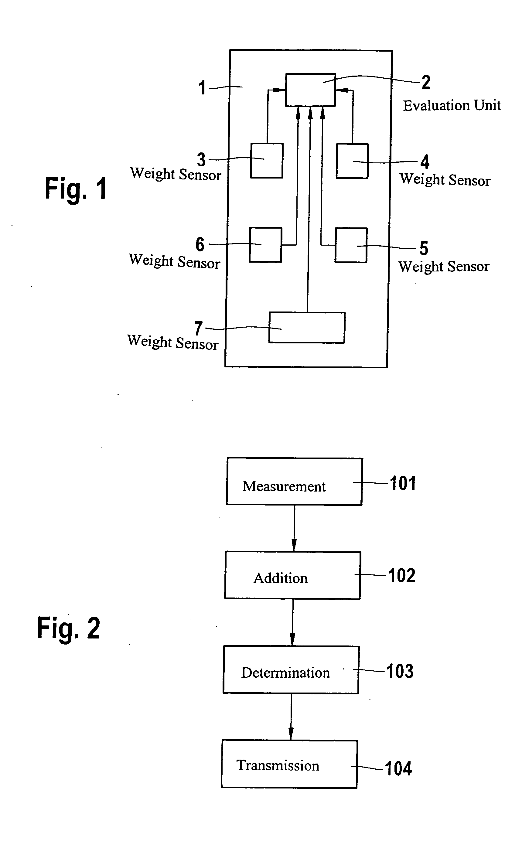
[0012] Since the introduction of the front passenger airbag, in the course of the improvement of restraint systems, sensors as well as processes have been introduced in the passenger compartment whose purpose is to classify the persons in the compartment. Essentially, the purpose of these systems is to protect the passenger properly in the event of a collision depending on the passenger's mass. For this purpose, various systems will be available in the future that will measure or, as necessary, estimate the mass of the occupant. Additional processes for monitoring the passenger compartment with the aid of video cameras or ultrasonic sensing systems will be designed.
[0013] For determining the total mass of a vehicle, various methods exist that estimate the total mass based on tire pressure, or that estimate the total mass by way of the suspension properties.
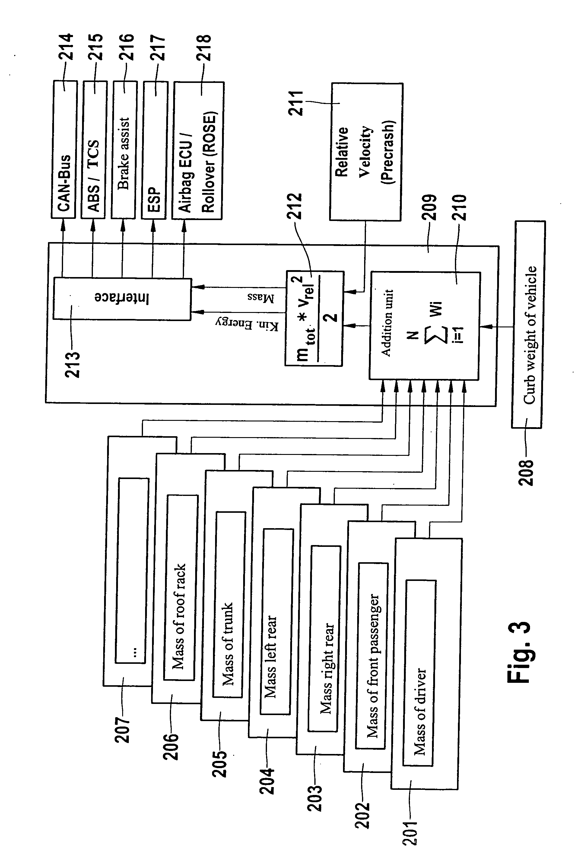
[0014] The present invention introduces an apparatus that determines the total mass of the vehicle in a simpler way. It uses in particular and preferably the future vehicle interior sensing system to determine the total mass. In this context, a stored value relating to the curb mass of the vehicle and measured values relating to the payload in the vehicle are added together in order to determine the total mass of the vehicle. For example, weight systems for the occupants that determine the mass or weight as an absolute value are used. The total mass is determined by simply adding together the individual masses and finally adding this to the curb weight.
[0015] A further improved calculation may also be accomplished if the trunk and/or the roof rack are also equipped with additional weight sensors. The measurement of the mass on the roof rack may be accomplished, for example, by four washers on the vehicle or through the use of four load-sensing bolts. The determination in the trunk may be accomplished, for example, by a pressure sensor film distributed in an appropriate manner in the trunk.
[0016] The total mass of the vehicle may also be determined by wheel bearing load sensors. The individual weight of the wheels is known for each vehicle and may be taken into account in the evaluation. In this way, the precisely measured total weight of the vehicle including occupants and luggage is obtained.
[0017] The resulting advantage is manifest in the event of an accident. Here, mass plays an important role because of the kinetic energy that occurs. The formula for calculating kinetic energy is: E = 1 2 · m · v 2
where m is the total mass of the vehicle in kilograms and v is the velocity of the vehicle or the velocity differential with respect to the impact object in meters per second.
[0018] As already described above, the total mass of the vehicle was determined, and the relative velocity of the vehicle as the vehicle is traveling with respect a different object is obtained using a pre-crash sensing system. This is a further input parameter in the evaluation electronics for determining the kinetic energy.
[0019] Taking into account the total mass, a controlled strategy for triggering the restraint systems may optionally be developed. A further advantage results for determining the center of mass of the vehicle. Since the distribution of the mass in the vehicle is known based on the various pieces of information, the center of mass of the vehicle may also be determined more effectively. In addition to the classic crash situation, this is also critical for rollover situations in order to be able to determine the vehicle's propensity to tip over more precisely and to trigger the head airbags at precisely the right time.
[0020] In addition to crash behavior, other systems may also use this information. This includes systems for improving the characteristics regarding dynamics of vehicular operations or braking performance such as ABS, TCS, ESP, or the brake assist.
[0021]FIG. 1 shows a block diagram for the apparatus according to the invention. A vehicle 1 contains an evaluation unit 2 to which weight sensors 3, 4, 5, 6, and 7 are connected via corresponding data inputs. Weight sensors 3, 4, 5 and 6 are provided for occupant seats in order to determine the weights of the various occupants as needed. Weight sensor 7 is used to measure the weight of the luggage or other objects stored in the vehicle. Many more weight sensors than those shown here may be used. For example, a weight sensor may also be provided for a roof luggage rack, implemented by using corresponding washers.
[0022] Evaluation unit 2 processes the data from weight sensors 3 to 7 and, from these values, determines a total mass value. This total mass value is added to the curb mass of the vehicle in order to determine the total mass of the vehicle. The curb weight or curb mass of the vehicle is permanently stored in a memory in evaluation unit 2. Alternatively, wheel bearing load sensors may be provided to determine the total weight or total mass of the vehicle. The total individual weights of the wheels must then also be taken into account. The total mass may then be used as a parameter for other vehicle systems. For example, the kinetic energy in the event of a collision may be calculated from the total mass in combination with a velocity relative to an impact object, and this kinetic energy is important to restraint systems, braking systems, and vehicle dynamic systems in order to protect vehicle occupants as effectively as possible.
[0023]FIG. 2 shows in a flowchart the process flow of the apparatus according to the invention. In method step 101, weight sensors 3 to 7 measure the weight that is applied to them. In method step 102, evaluation unit 2 adds the weights that were determined by weight sensors 3 to 7 and from this value determines the corresponding mass. In method step 103, evaluation unit 2 then loads the curb weight or curb mass of vehicle 1 from a memory and adds it to the measured total weight in order to determine the total mass of vehicle 1 including the cargo and occupants. This value is then passed to other vehicle systems in method step 104 in order to optimize the function of these vehicle systems.
[0024]FIG. 3 shows in a block diagram the apparatus according to the invention. Sensors 201 to 207 are connected by corresponding data inputs to an evaluation unit 209 that adds up the measured weight values. In this context, sensor 201 determines the mass of the driver, sensor 202 determines the mass of the front passenger, sensor 203 determines the mass of the right rear passenger, sensor 204 determines the mass of the left rear passenger, sensor 205 determines the mass of the cargo weight in the trunk, sensor 206 determines the mass of the load that is applied on the roof rack, and sensor 207 may be used for additional locations in the vehicle where a load or a passenger may be present, for example in the middle of the rear seat.
[0025] Addition unit 209 is connected by a further input 208 to a memory 209 in which the curb weight of the vehicle is stored. Addition unit 210, an additional calculation unit 212, and an interface 213 are located in a vehicle system 209 that performs the evaluation here. Addition unit 210 passes the totaled value to calculation unit 212, to which a pre-crash sensing system 211 is also connected. Pre-crash sensing system 211 supplies the relative velocity with respect to an object with which a collision may occur to calculation unit 212. From the total mass and the relative velocity, calculation unit 212 calculates the kinetic energy that would be applied in the event of a collision with the respective object. It is possible to integrate calculation unit 212 or addition unit 210 into a particular vehicle system. Calculation unit 212 then sends to interface 213 the values for the kinetic energy and the mass that the interface distributes to additional vehicle systems, for example via a CAN bus 214. These additional vehicle systems include ABS or TCS, brake assist, ESP or a restraint system 218. Systems 215 to 218 may be connected to interface 213 either via CAN bus 214 or via corresponding paired wire cables.

PUM

no PUM

Description & Claims & Application Information

We can also present the details of the Description, Claims and Application information to help users get a comprehensive understanding of the technical details of the patent, such as background art, summary of invention, brief description of drawings, description of embodiments, and other original content. On the other hand, users can also determine the specific scope of protection of the technology through the list of claims; as well as understand the changes in the life cycle of the technology with the presentation of the patent timeline. Login to view more.

Similar technology patents

Photographing system

InactiveUS20070064119A1High accuracyTelevision system detailsColor signal processing circuitsColor correctionColor image
Owner:OLYMPUS CORP

Classification and recommendation of technical efficacy words

  • Reduce severity
  • High accuracy

Inhibition of irritating side effects associated with use of a topical ophthalmic medication

InactiveUS20050004074A1Reduce severityEffective deliveryPowder deliveryBiocideCyclodextrin derivativeCyclodextrin Derivatives
Owner:ALLERGAN INC

Modulators of ATP-Binding Cassette Transporters

ActiveUS20100184739A1Reduce severityBiocideSenses disorderDiseaseTranslocator protein
Owner:VERTEX PHARMA INC
Why Eureka
Try Eureka