Organic electroluminescent apparatus

a technology of electroluminescent apparatus and electroluminescent light, which is applied in the direction of discharge tube luminescnet screen, energy-saving lighting, sustainable buildings, etc., can solve the problems of reducing luminous efficiency, increasing power consumption, and complicating the manufacturing process, and achieves the effect of improving luminous efficiency

Inactive Publication Date: 2006-05-25
SANYO ELECTRIC CO LTD
View PDF0 Cites 20 Cited by
  • Summary
  • Abstract
  • Description
  • Claims
  • Application Information

AI Technical Summary

Benefits of technology

[0013] It is an object of the invention to provide an organic electroluminescent apparatus that allows the luminous efficiency to be improved.

Problems solved by technology

This complicates the manufacturing process.
However, in organic EL apparatuses in the first and second arrangements described above, light from the white light emitting device is transmitted through the color filter layers to obtain light in the three primary colors and is greatly attenuated.
Consequently, the luminous efficiency is lowered, and the power consumption is raised.

Method used


Image

  • Organic electroluminescent apparatus
  • Organic electroluminescent apparatus
  • Organic electroluminescent apparatus

Examples


first embodiment

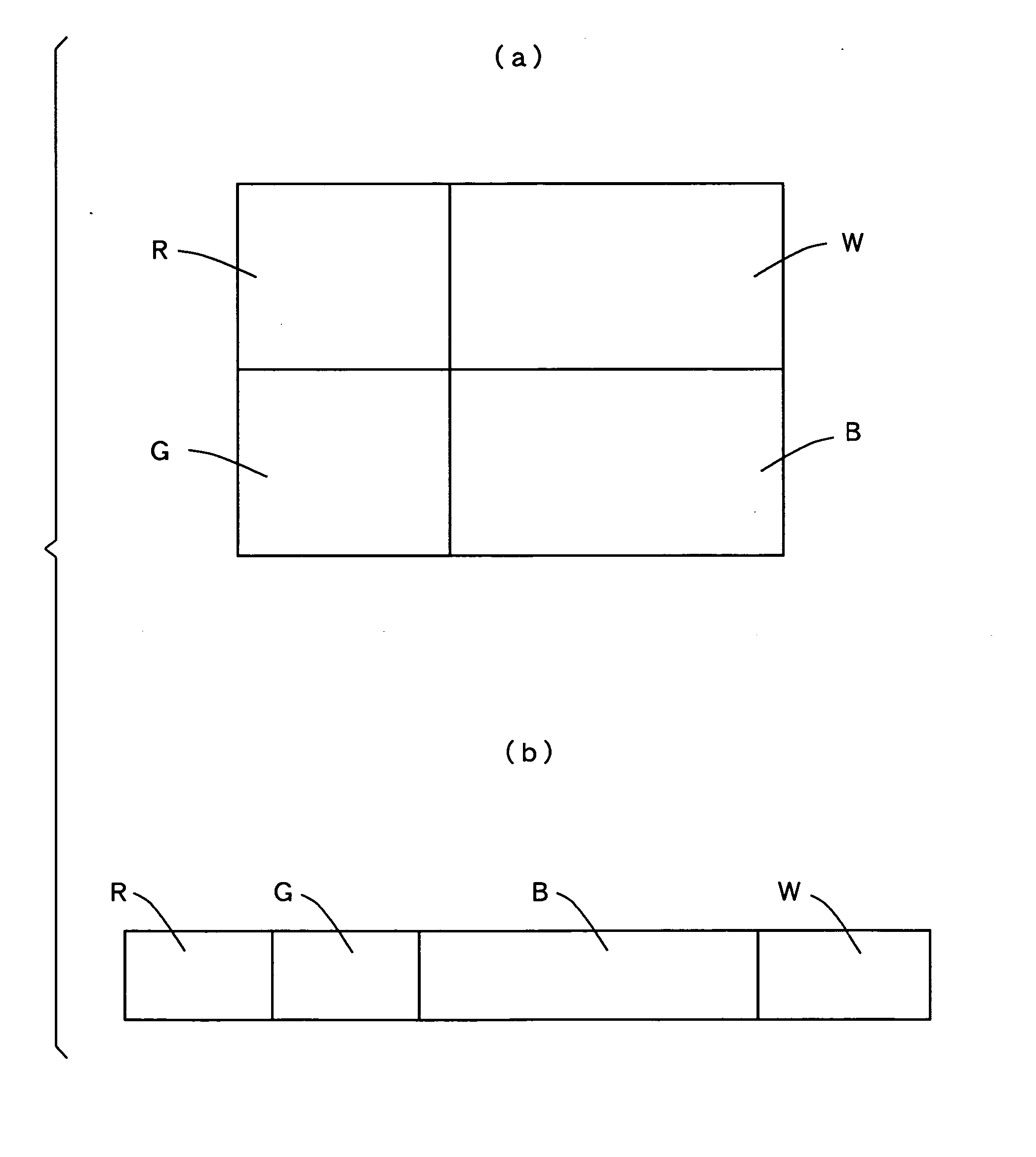
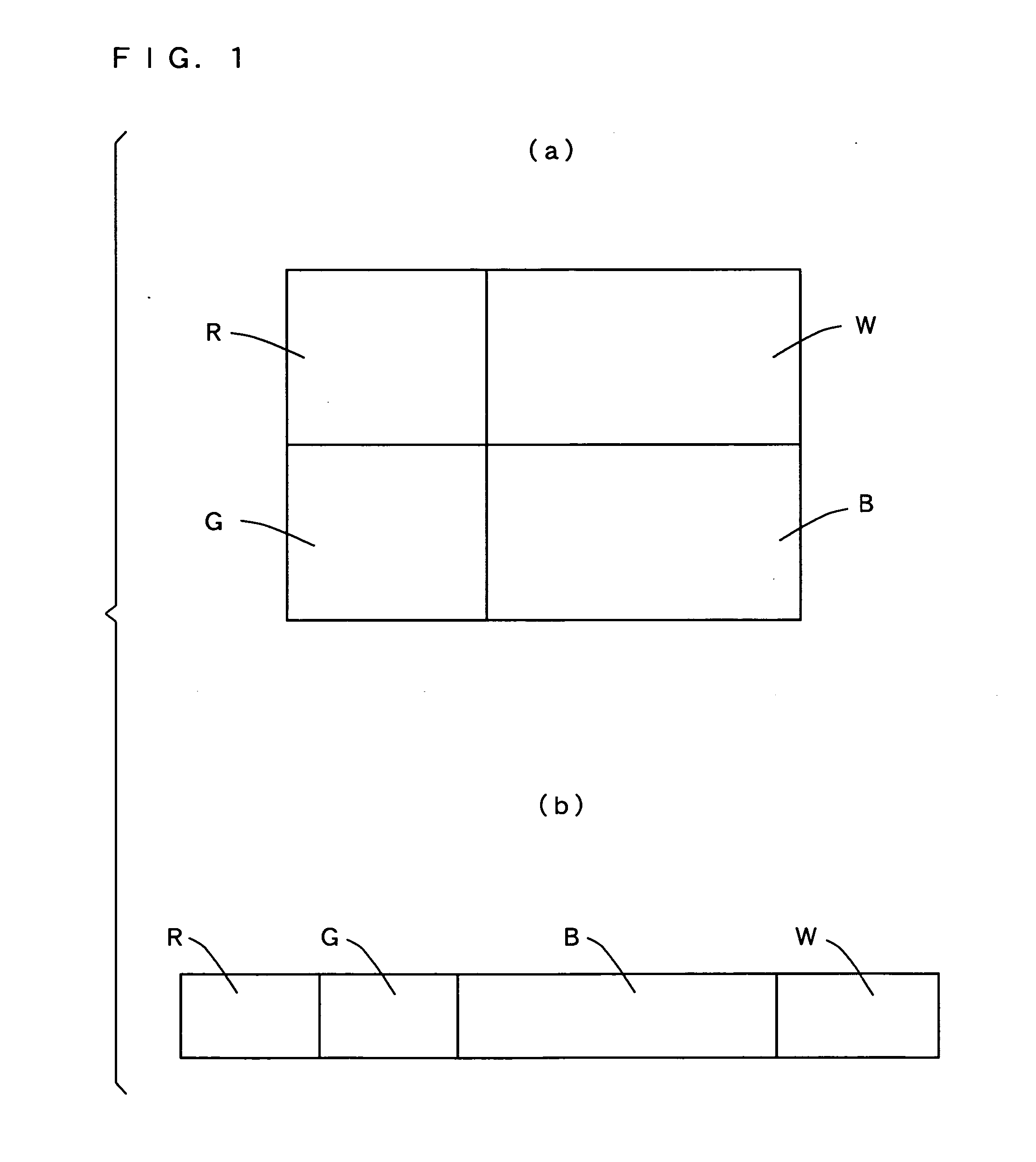
[0071] FIGS. 1(a) and 1(b) are top views each showing the arrangement of the light emitting region of a pixel in an organic EL apparatus according to a first embodiment of the invention. Note that in FIGS. 1(a) and 1(b), the region that emits red light is denoted by R, the region that emits green light by G, the region that emits blue light by B, and the region that emits white light by W.

[0072] As shown in FIG. 1(a), the regions R, G, B, and W are for example provided in the upper left, lower left, lower right, and upper right regions, respectively that are produced by dividing a square into four.

[0073] As shown in FIG. 1(b), the regions R, G, B, and W may be aligned in this order.

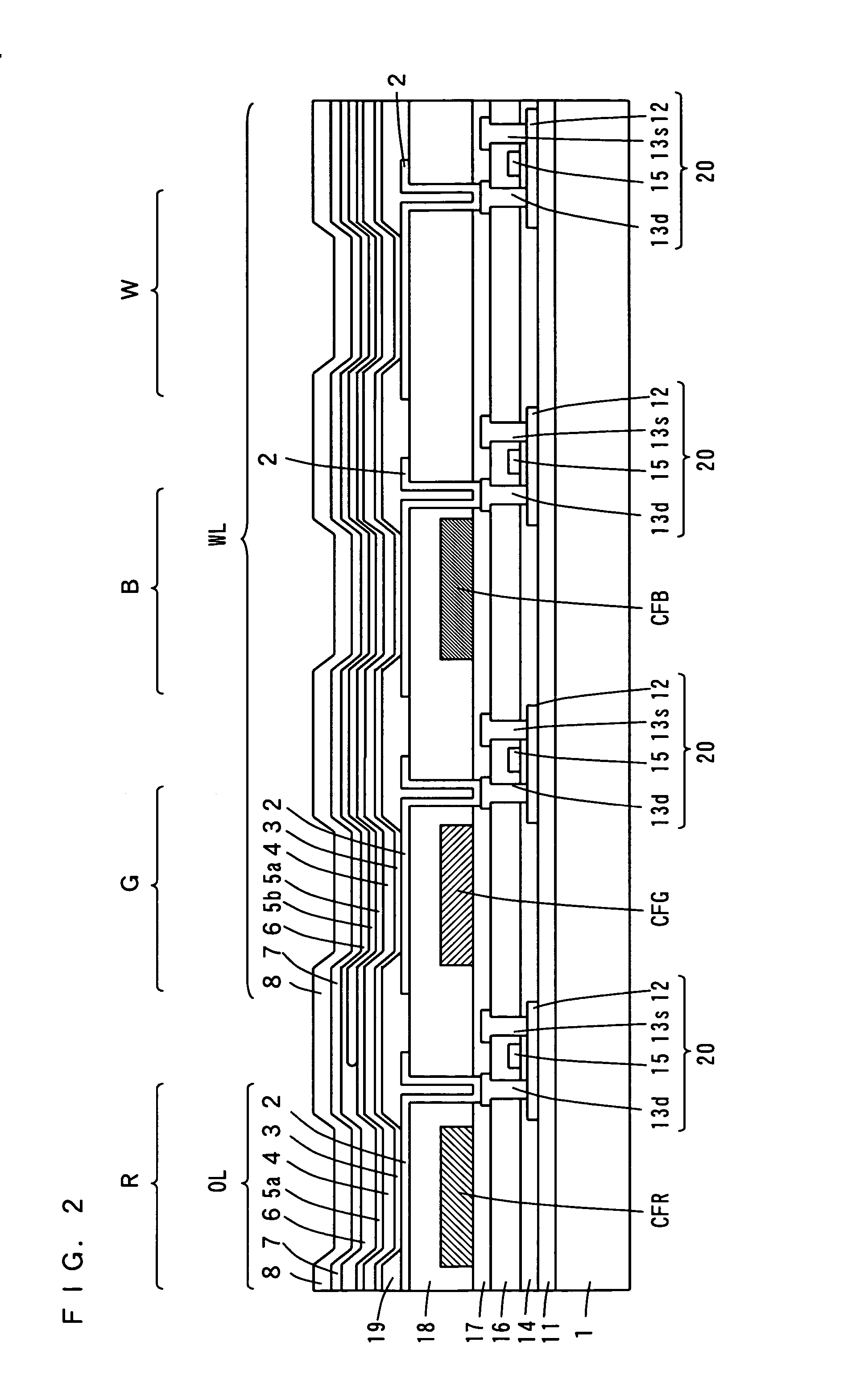
[0074]FIG. 2 is a sectional view of an example of an arrangement of an organic EL apparatus according to the first embodiment.

[0075] The example in FIG. 2 and following other examples of organic EL apparatuses shown in sectional views correspond to the top view in FIG. 1(b). Therefore, the organic EL ...

second embodiment

[0198] Regarding an organic EL apparatus according to a second embodiment of the invention, combinations of a plurality of organic EL devices will be referred to as modes. First to seventh modes in the following description are the same as the first to seventh modes according to the first embodiment described above.

[0199]FIG. 7 is a sectional view of an example of the structure of an organic EL apparatus according to the second embodiment. The organic EL apparatus shown in FIG. 7 is different from the organic EL apparatus shown in FIG. 2 in the following points.

[0200] In the organic EL apparatus shown in FIG. 7, similarly to the organic EL apparatus in FIG. 2, a layered film 11, TFTs 20, a first interlayer insulating film 16, a second interlayer insulating film 17, a first planarization layer 18, a second planarization layer 19, and an organic EL device are formed on a substrate 1.

[0201] A green color filter layer CFG and a blue color filter layer CFB are provided side by side ab...

third embodiment

[0249] The structure of an organic EL apparatus according to a third embodiment of the invention is different from that of the organic EL apparatus in FIG. 2 in that an organic EL device WL is not formed in the position corresponding to the region W in FIG. 1(b).

[0250] In the organic EL apparatus according to the embodiment, combinations of a plurality of organic EL devices will also be referred to as modes.

[0251] FIGS. 10(a) to 10(f) are views showing the structures of organic EL apparatuses based on a plurality of modes according to the third embodiment.

[0252]FIG. 10(a) is a view showing the structure of an organic EL apparatus based on an eighth mode (RwGw-Bb).

[0253] According to the organic EL apparatus based on the eighth mode, red light and green light can be obtained based on white light from an organic EL device WL, and blue light can be obtained from an organic EL device BL that emits blue light.

[0254] As shown in FIG. 10(a), the organic EL device WL is formed on a hol...


PUM


Abstract

A red color filter layer is provided under an organic EL device. A green color filter layer, a blue color filter layer, and a region without a color filter layer are provided in this order under an organic EL device. Orange light from the organic EL device is transmitted through the red color filter layer, so that red color is obtained. White light from the organic EL device is transmitted through the green color filter layer and the blue color filter layer, so that green light and blue light are obtained. White light is obtained from the organic EL device. In this way, red light, green light, blue light, and white light are obtained.

Description

BACKGROUND OF THE INVENTION [0001] 1. Field of the Invention [0002] The present invention relates to an organic electroluminescent apparatus. [0003] 2. Description of the Background Art [0004] In recent years, as various kinds of information equipment have come to be used, there has been an increasing demand for flat panel display devices that can be used with less power consumption than generally used CRTs (Cathode Ray Tubes). Thin and lightweight organic electroluminescent (hereinafter abbreviated as “organic EL”) devices having high efficiency and low angular-field-of-view dependency have attracted attention as one type of such flat panel display devices, and displays using the organic EL devices have actively been developed. [0005] The organic EL device is a self-light emitting device in which electrons and holes from an electron injection electrode and a hole injection electrode, respectively are injected to a light emitting portion, and the injected electrons and holes are rec...

Claims


Application Information

Patent Timeline
Patent Type & Authority Applications(United States)
IPC IPC(8): H01L51/52H05B33/02
CPCC09K11/06C09K2211/1011C09K2211/1037H01L27/3213H01L27/322H05B33/14Y02B20/181Y02B20/00H10K59/351H10K59/38H05B33/22
Inventor NISHIMURA, KAZUKIHASHIMOTO, HARUHISAIYORI, MASAHIROHAMADA, YUJI
Owner SANYO ELECTRIC CO LTD
Why Eureka
Try Eureka