Side-suction heat dissipating structure for an industrial computer

a heat dissipating structure and industrial computer technology, applied in computing, cooling/ventilation/heating modifications, instruments, etc., can solve the problems of easy expulsion of heat, unsatisfactory heat dissipation, and the cpu also generates the most heat, so as to reduce the distance between the fans and the cpu, increase the suction force, and reduce the distance of heat suction inside the wind shade

Inactive Publication Date: 2006-05-25
HUNG KUO CHUAN
View PDF1 Cites 10 Cited by
  • Summary
  • Abstract
  • Description
  • Claims
  • Application Information

AI Technical Summary

Benefits of technology

[0008] Accordingly, a CPU that is originally located at the center will be moved backward to be closer to the back panel of the casing, therefore, the distance between the fans and the CPU will be reduced, and, correspondingly, the distance of heat suction inside the wind shade is also reduced, thereby increasing the strength of suction force; moreover, as the fins are inside the wind shade with an inward opening, when the rear fans start to expel heat, a kind of ventilation function can be generated, which can also expel heat generated by several heating elements on the motherboard, thereby achieving the object of improving the efficiency of heat dissipation. In addition, using several fans can greatly increase the suction force without the effect that the overall function of heat dissipation is lost when one of the fans fails, because when one of the fans fails, the rest of the fans can be still functioning, to achieve the object of dissipating heat continuously.

Problems solved by technology

As a CPU of an industrial computer usually consumes higher power, the CPU also generates the most heat.
In general, as shown in FIG. 1, a heat dissipater b is emplaced on the top of a heat source a to conduct the heat generated by the heat source to the heat dissipater b, and a fan c is used to dissipate the heat and expel through a rear vent d. This kind of heat dissipation configuration can achieve the function of heat dissipation, however, due to that the heat source is entirely confined in a heat dissipater with limited heat dissipation area in a short time, and accumulates continuously, it is not very easy to expel heat within a short time; besides, due to that this kind of heat dissipater requires very long time to achieve the function of heat dissipation, this kind of heat dissipation is not perfect.

Method used


Image

  • Side-suction heat dissipating structure for an industrial computer
  • Side-suction heat dissipating structure for an industrial computer
  • Side-suction heat dissipating structure for an industrial computer

Examples


Embodiment Construction

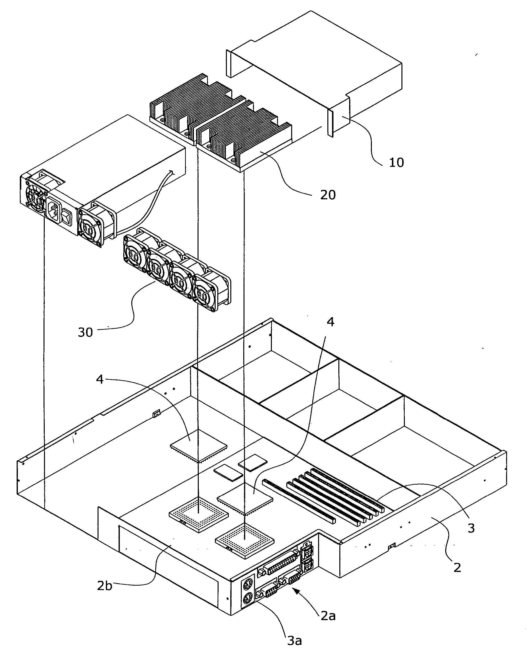
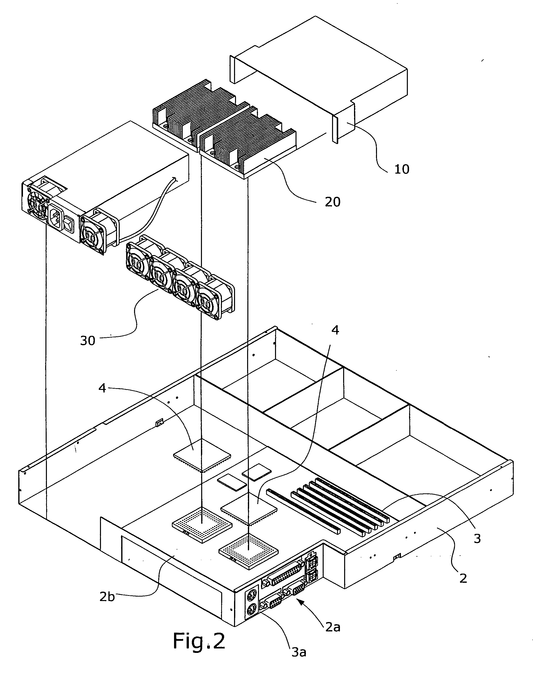
[0015] Referring to FIG. 2 and FIG. 3, the present invention comprises primarily a wind shade 10, fins 20, and several fans 30, wherein, an indented gap 2a is formed at the rear part of one side of a computer casing 2 for providing for an input / output connecting interface 3a on a motherboard 3, the motherboard 3 is rotated by 90 degrees counter-clockwise and fixed inside the casing 2, the input / output connecting interface 3a on the motherboard 3 passes through the indented gap 2a, and fins 20 are emplaced inside the wind shade 10, such that the bottom of fins 20 can be tightly attached to the top of CPU 4; then, the wind shade 10 is connected to the back panel 2b of the casing 2 to contain several fans 30 in the interior space of the connecting place, thereby dissipating heat in an outward suction way.

[0016] Referring to FIG. 4A and FIG. 4B, which show two schematic views of the implementation for the present invention, a CPU 4 will be moved backward to be closer to a back panel 2b...


PUM


Abstract

A side-suction heat dissipating structure for an industrial computer comprises primarily a wind shade, fins, and fans to quickly expel heat generated by a CPU inside of an industrial computer, preventing from the impact to overall efficiency by the accumulation of heat. The features include that a motherboard is rotated by 90 degrees counter-clockwise and fixed inside a computer casing, that fins are emplaced inside a wind shade such that the bottom of fins can be tightly attached to the top of CPU enabling the alignment of heat flow inside the computer casing with the direction of overall heat dissipating, and reducing the distance from CPU to the back panel of the computer casing, thereby improving the efficiency of heat dissipation.

Description

BACKGROUND OF THE INVENTION [0001] a) Field of the Invention [0002] The present invention relates to a side-suction heat dissipating structure for an industrial computer, and more particularly to a structure wherein a motherboard is rotated by 90 degrees counter-clockwise, to minimize the distance from a CPU (Central Processing Unit) to the rear part of the computer casing, and align with the direction of overall heat dissipation, thereby improving the efficiency of heat dissipation. [0003] b) Description of the Prior Art [0004] As a CPU of an industrial computer usually consumes higher power, the CPU also generates the most heat. Because the built-in space for heat dissipation inside a computer casing is limited, and conventionally, the heat dissipation space for an industrial server is smaller than that of a desktop computer, hence a variety of configuration are used for the structure of heat dissipation. In general, as shown in FIG. 1, a heat dissipater b is emplaced on the top o...

Claims


Application Information

Patent Timeline
Patent Type & Authority Applications(United States)
IPC IPC(8): H05K7/20
CPCG06F1/20H05K7/20727
Inventor HUNG, KUO-CHUAN
Owner HUNG KUO CHUAN
Why Eureka
Try Eureka