
Image signal, processing device and processing method, coefficient data generation device and generation method used for the same, program for executing the methods and computer readable medium containing the program

a technology of image signal and coefficient data, applied in the field of apparatus and a processing method for an image signal, a device and a generation method for generating coefficient data, can solve the problems of blotchy noise, so-called block noise (block distortion) in some cases, and portions such as edges subject to a steep change in luminance may be subject to blotchy noise and other problems, to achieve the effect of improving the quality of the second image signal

Inactive Publication Date: 2006-05-25
SONY CORP
View PDF23 Cites 14 Cited by
  • Summary
  • Abstract
  • Description
  • Claims
  • Application Information

AI Technical Summary

Benefits of technology

[0011] It is an object of the present invention to provide an apparatus for processing an image signal etc. that allow improvements in quality of a second image signal to be easily realized.
[0019] By performing motion compensation on the frames before and after the current frame by using the motion vector stored in the plurality of frame memory portions together with the pixel data, plural items of pixel data selected from the frames before and after the current frame are provided with high correlation with plural items of pixel data selected from the current frame, thereby enabling improvements in quality of the second image signal to be easily realized.
[0021] Further, each of the frame memory portions may be constituted of a plurality of banks, and the frame is divided in units of major block in which a plurality of minor blocks is arranged two-dimensionally so that the minor blocks located at different positions in the major block may be stored in each of the plurality of banks. It is thus possible to concurrently read from the plurality of banks the plural items of pixel data used when generating the pixel data of the target position in the second image signal, thereby enhancing a speed for generating the pixel data.
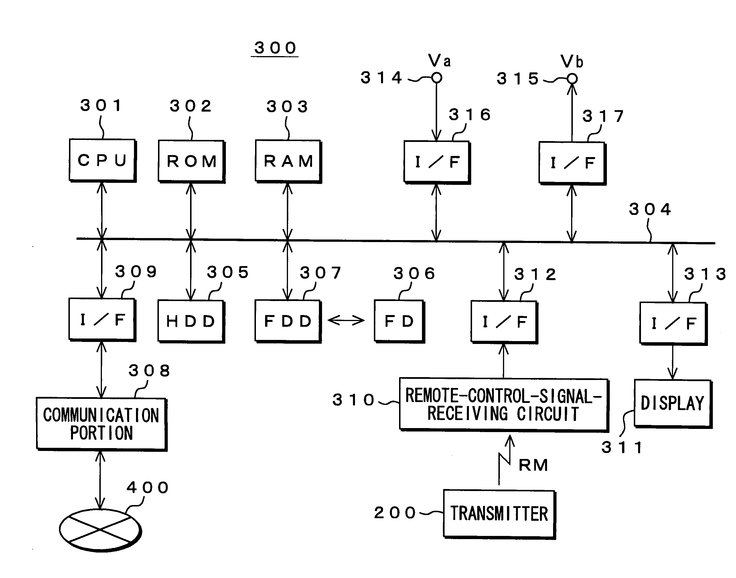
[0028] In such a manner, although the coefficient data for an estimation equation is generated which is used when converting the first image signal into the second image signal, when converting the first image signal into the second image signal, pixel data of the target position in the second image signal is calculated by using the estimation equation. It is thus possible to easily realize improvements in quality of the second image signal in the case of converting the first image signal into the second image signal by using the estimation equation.

Problems solved by technology

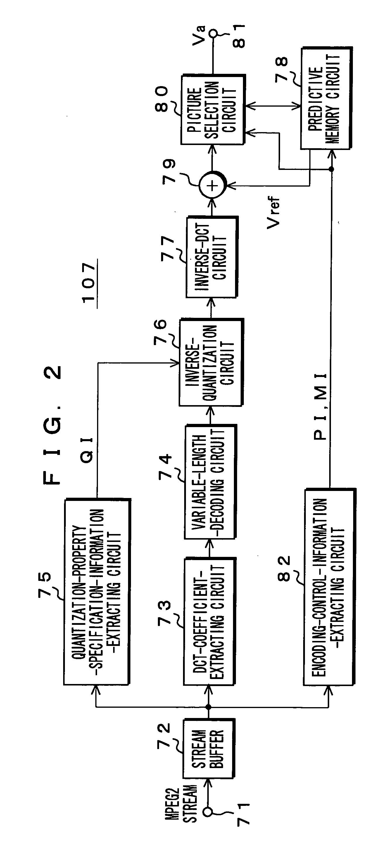
However, coding accompanying DCT is block-unit processing, so that as a compression ratio increases, block-shaped noise, so-called block noise (block distortion) may occur in some cases.
Further, a portion such as an edge subject to a steep change in luminance may be subject to blotchy noise, that is, mosquito noise due to coarse quantization of a high-frequency component.

Method used


Image

  • Image signal, processing device and processing method, coefficient data generation device and generation method used for the same, program for executing the methods and computer readable medium containing the program
  • Image signal, processing device and processing method, coefficient data generation device and generation method used for the same, program for executing the methods and computer readable medium containing the program
  • Image signal, processing device and processing method, coefficient data generation device and generation method used for the same, program for executing the methods and computer readable medium containing the program

Examples


Embodiment Construction

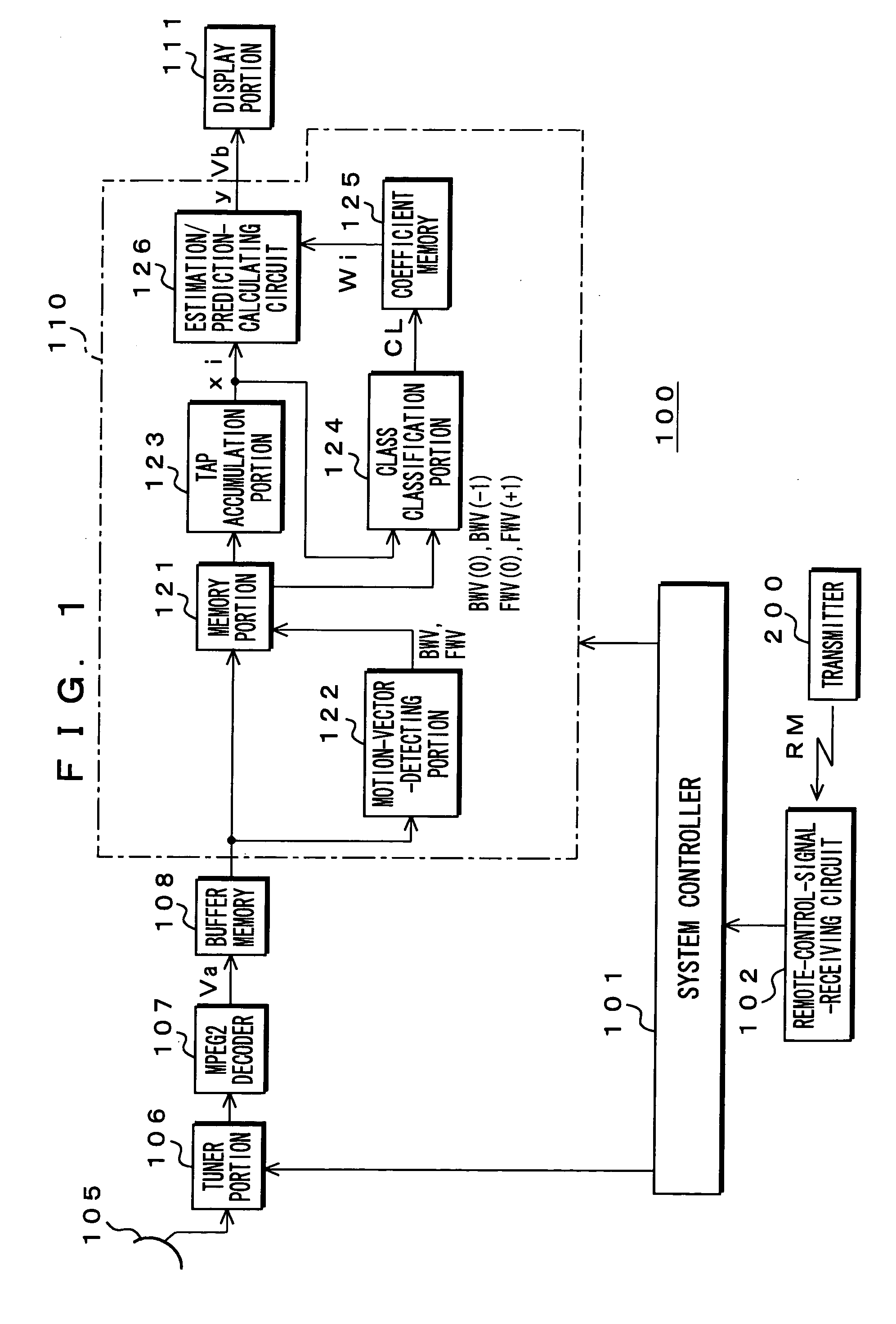
[0042] The following will describe embodiments of the present invention with reference to drawings. FIG. 1 shows a configuration of a digital broadcast receiver 100 according to an embodiment.

[0043] This digital broadcast receiver 100 is equipped with a microcomputer and has a system controller 101 for controlling operations of an entire system and a remote-control-signal-receiving circuit 102 for receiving a remote-control signal RM. The remote-control-signal-receiving circuit 102 is connected to the system controller 101. This remote-control-signal-receiving circuit 102 receives a remote-control signal RM, which is output from a remote-control transmitter 200 in response to a user operation and supplies an operation signal in accordance with this signal RM to the system controller 101.

[0044] The digital broadcast receiver 100 further has a receiving antenna 105 and a tuner portion 106. The tuner portion 106 is supplied with a broadcast signal (modulated RF signal) taken by the r...


PUM


Abstract

The present invention relates to an apparatus for processing an image signal etc. that are well applicable to removal of coding noise from, for example, an image signal. Based on five consecutive frames of an image signal Va, a memory portion 121 outputs as pixel data xi of predictive taps plural items of pixel data located in a space directional and time directional peripheries with respect to a target position in an image signal Vb. In the case, frames before and after a current frame are subjected to motion compensation by using a motion vector. A class classification portion 124 obtains a class code CL indicating a class to which pixel data of the target position in the image signal Vb belongs, by using the pixel data xi and motion vectors BWV(0), BWV(−1), FWV(0), and FWV(+1). A calculating circuit 126 obtains pixel data y of the target position in the image signal Vb based on an estimation equation by using the pixel data xi and coefficient data Wi that corresponds to the class code CL.

Description

TECHNICAL FIELD [0001] The present invention relates to an apparatus and a method for processing an image signal, a device and a method for generating coefficient data used by them, a program for performing these methods, and a computer-readable medium for recording the program. [0002] More specifically, the present invention relates to an apparatus for processing an image signal etc. in which pixel data of a plurality of consecutive frames of a first image signal is stored beforehand in a plurality of frame memory portions together with a motion vector between mutually adjacent frames corresponding to this pixel data; plural items of pixel data located in a periphery in a space direction with respect to a target position in a second image signal are selected from a frame memory portion in which a current frame is stored and plural items of pixel data located in a periphery in the space direction with respect to a position obtained by performing motion compensation on the target pos...

Claims


Application Information

Patent Timeline
IPC IPC(8): G06K9/36H04N19/50G06T7/20H04N19/102H04N19/134H04N19/136H04N19/139H04N19/167H04N19/189H04N19/19H04N19/196H04N19/423H04N19/44H04N19/503H04N19/51H04N19/513H04N19/61H04N19/625H04N19/86H04N19/91
CPCH04N19/136H04N19/117H04N19/51H04N19/85
Inventor KONDO, TETSUJIROWATANABE, TSUTOMU
Owner SONY CORP
Learn More