Method and apparatus for controlling motor drive

a technology of motor drive and motor drive, which is applied in the direction of motor/generator/converter stopper, electronic commutator, dynamo-electric converter control, etc., can solve the problems of excessive apparatus, excessive apparatus, and inability to rotate brushless motors at desired speed and torque, so as to avoid the upsizing and cost increase of the apparatus, improve the performance of pwm speed control, and control finer

Inactive Publication Date: 2006-05-25
NIDEC CORP
View PDF10 Cites 14 Cited by
  • Summary
  • Abstract
  • Description
  • Claims
  • Application Information

AI Technical Summary

Benefits of technology

[0015] Accordingly, each divided pulse width of the output signal is processed in the pulse width shorter than the divided pulse width by the correction pulse width by the regulation of the simple gating process with the pulse having the correction pulse width, which allows the electric power supply to the coil to be freely corrected by the amount corresponding to the correction pulse width from the electric power supply based on each divided pulse width. Therefore, the coil current of each phase of the brushless motor can be controlled more finely with the simple configuration when compared with the control of the output signal, the PWM speed control performance is improved while avoiding the upsizing and cost increase of the apparatus, and the rotating speed of the brushless motor can be controlled more finely.

Problems solved by technology

Therefore, even if duty ratio of a pulse-width of the PWM signal is, e.g., 20%, because the coil currents of the phases are not accurately controlled at magnitude of 20%, there is a fear that the brushless motor is not rotated at desired speed and torque.
In this case, upgrading of DSP or the motor control IC is required for such a vast change that the frequency (period) of the reference pulse signal is changed, which results in the problems that the apparatus becomes extremely expensive while a circuit scale of DSP or the motor control IC is enlarged to remarkably upsize the apparatus.
Therefore, it is impractical.
As a result, there are the problems that the apparatus becomes extremely expensive while the circuit scale of DSP or the motor control IC is enlarged to remarkably upsize the apparatus.
Thus, it is very difficult to take the countermeasure such as the increase in frequency (period) of the reference pulse signal, and conventionally it is impossible to control the rotating speed of the brushless motor more finely.
When the brushless motor drive control apparatus is not formed by DSP or the dedicated motor control IC, it is obvious that the above problems are also generated.

Method used


Image

  • Method and apparatus for controlling motor drive
  • Method and apparatus for controlling motor drive
  • Method and apparatus for controlling motor drive

Examples


first embodiment

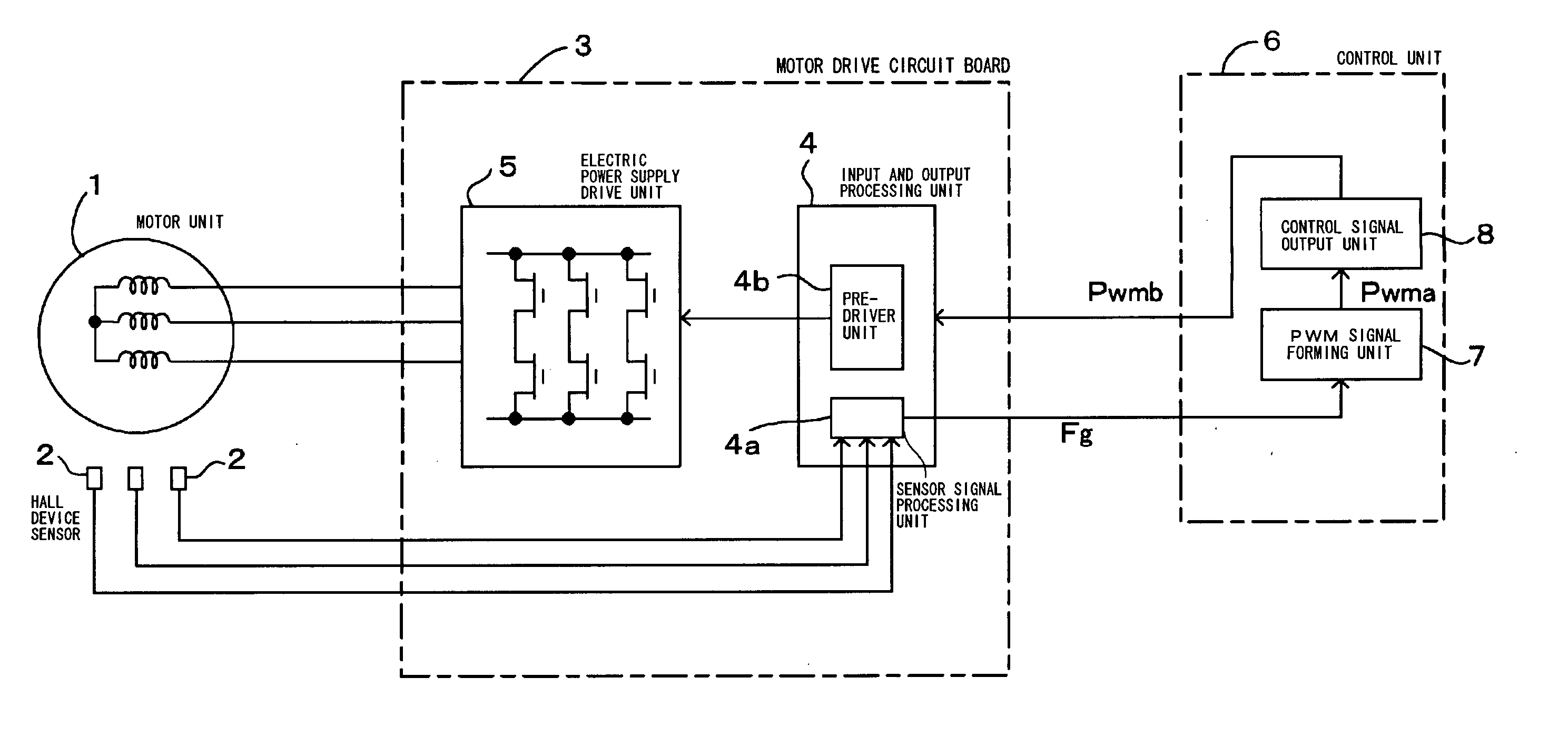
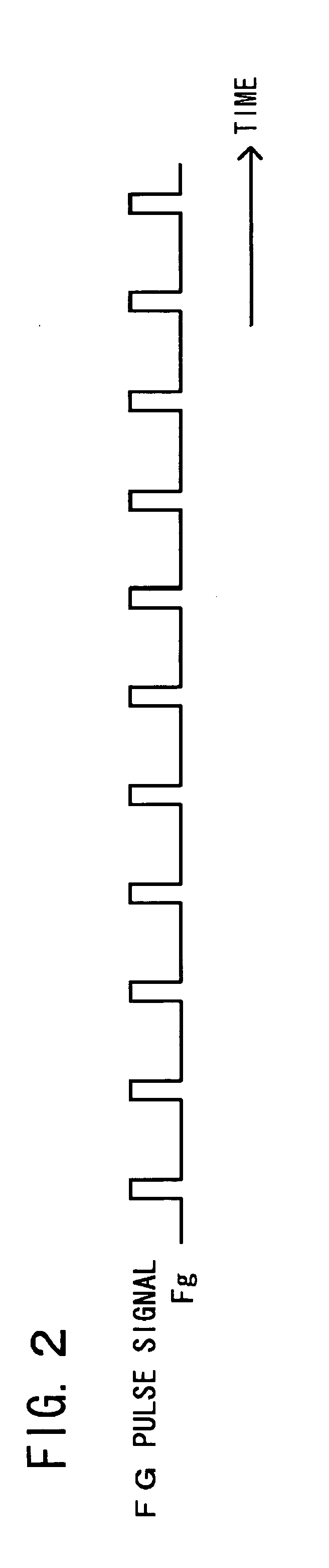
[0026] the invention will be described in detail with reference to FIGS. 1 to 5. FIG. 1 is a block diagram showing a motor drive control apparatus which performs the PWM speed control of the brushless motor. FIG. 2 is a waveform chart showing a speed-detection frequency pulse signal of the brushless motor. FIG. 3 is a flowchart showing the speed control of the motor drive control apparatus of FIG. 1. FIGS. 4 and 5 are waveform charts respectively for explaining the operation of each unit in the motor drive control apparatus of FIG. 1.

[0027] The brushless motor of FIG. 1 includes a motor unit 1, and the motor unit 1 includes a stator in which the coil is wound and a rotor having a circular rotor magnet. The brushless motor is the typical three-phase brushless motor used for various kinds of office automation equipment such as the sheet-feed motor of the printer, and the brushless motor is rotated at about 5000 rpm by the PWM speed control.

[0028] In order to detect the rotating speed...

second embodiment

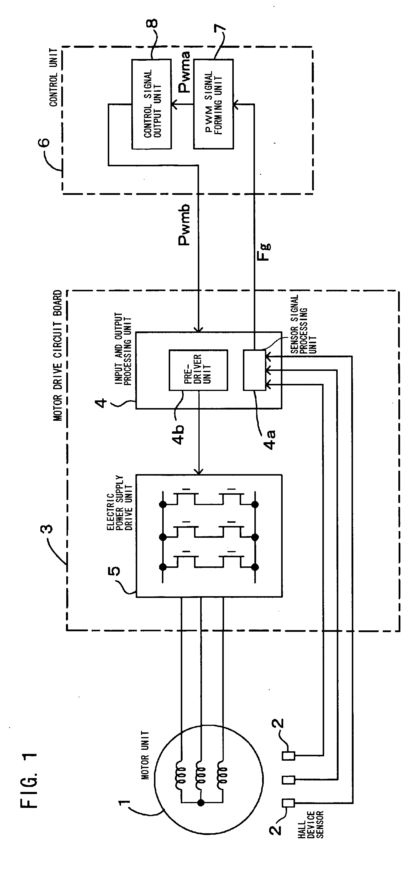
[0046] Then, the invention will be described in detail with reference to FIGS. 6 to 9.

[0047]FIG. 6 is a block diagram showing a motor drive control apparatus which performs the PWM speed control of the brushless motor. FIG. 7 is a flowchart showing the speed control of the brushless motor of FIG. 6. FIG. 8 is a detailed block diagram showing output correction means. FIG. 9 is a waveform chart for explaining the operation of the output correction means of FIG. 8.

[0048] In the second embodiment, the control unit 6 of the first embodiment of FIG. 1 is further improved. In FIGS. 6 and 7, the component designated by the same numeral as FIGS. 1 and 3 shall be the same or corresponding component, and the detailed description will not be made.

[0049] When the setting speed of the brushless motor is decreased compared with the brushless motor of the first embodiment, the speed control is set by the gain adjustment amount. For example, it is desired that the setting and the control are perfo...


PUM


Abstract

In the invention, a PWM signal is formed at a frequency of a reference pulse signal, the PWM signal which has a pulse width being changed according to a frequency difference between an FG pulse signal for detecting a speed of a brushless motor and the reference pulse signal of a target speed, an output signal for PWM control is formed by an N-fold frequency of the PWM signal, the output signal for PWM control in which a pulse having the divided pulse width is arranged in each N-divided period, the N-divided period in which each one period of the PWM signal is divided by N, and electric power supply to a coil of each phase of the brushless motor is turned on and off at intervals shorter than that of the output signal control without increasing the frequency of the reference pulse signal. Therefore, speed control performance of the brushless motor is improved while avoiding the upsizing and const increase of the apparatus

Description

BACKGROUND OF THE INVENTION [0001] 1. Field of the Invention [0002] The present invention relates to a method and apparatus for controlling motor drive in which a brushless motor is driven by PWM speed control. [0003] 2. Description of the Related Art [0004] Conventionally this kind of brushless motor (also referred to as brushless DC motor or brushless AC motor) typified by a three-phase brushless motor is used for driving various kinds of office automation equipment such as a sheet-feed motor of a printer. In order to accurately drive the brushless motor at a setting speed, the PWM speed control is frequently used as speed control of the brushless motor. [0005] When the PWM speed control is performed by detecting a frequency according to a rotating speed of the brushless motor, an FG sensor is used as means for detecting the rotating speed of a rotor of the brushless motor. A PWM signal is formed at the frequency of a reference pulse signal such that the frequency (phase) of a fre...

Claims


Application Information

Patent Timeline
Patent Type & Authority Applications(United States)
IPC IPC(8): H02P7/06H02P6/06H02P6/08H02P6/17
CPCH02P6/06
Inventor HARADA, KOJI
Owner NIDEC CORP
Why Eureka
Try Eureka