Pump system with vacuum source

a pump system and vacuum pump technology, applied in the field of pumps, can solve the problems of reducing affecting causing the fluid inside the reservoir to splash, mist, or otherwise enter the inlet, so as to reduce the reliability of the system, increase the distance, and reduce the effect of reliability

Inactive Publication Date: 2006-05-25
MULTIQUIP
View PDF13 Cites 12 Cited by
  • Summary
  • Abstract
  • Description
  • Claims
  • Application Information

AI Technical Summary

Benefits of technology

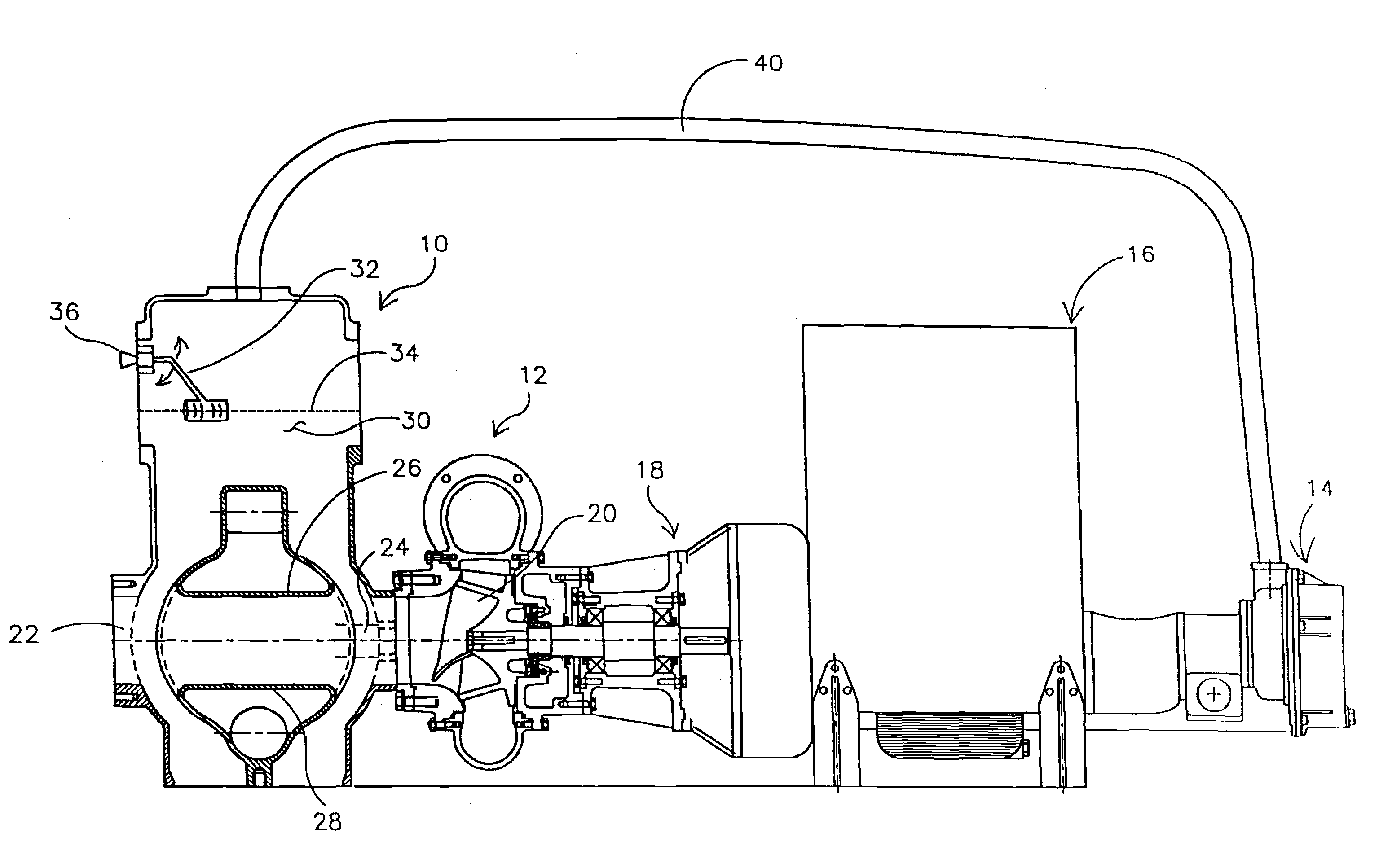
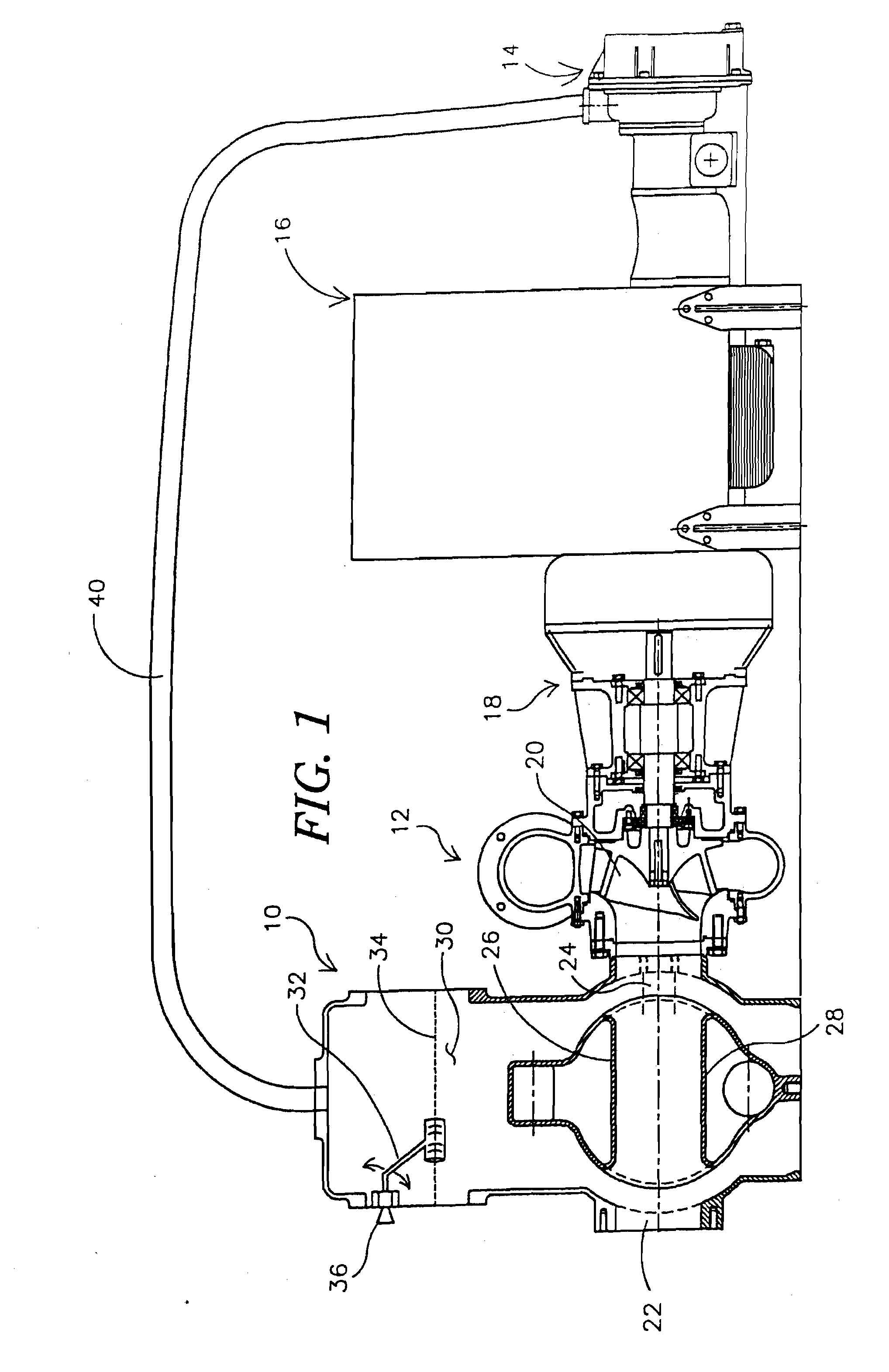
[0007] Under neutral or negative head pressure, the vacuum pump causes air to flow from the reservoir into the vacuum pump. It has been found that this airflow, along with vibration or movement of the pump, may cause the pumped fluid inside the reservoir to splash, mist, or otherwise enter the inlet of the vacuum pump. This fluid, which may include sediments or the like, may cause damage to the vacuum pump. In cold weather applications, the fluid may also dilute any antifreeze used in the vacuum pump system, which can reduce the reliability of the system.
[0008] To help reduce the possibility that the pumped fluid will enter the vacuum pump system, a deflector may be provided in the reservoir, preferably between the inlet to the vacuum pump and the pumped fluid in the reservoir. This deflector is preferably adapted to deflect or otherwise reduce the possibility that the fluid in the reservoir will enter the inlet of the vacuum pump. Alternatively, or in addition, an extension may be provided on top of the separator. This extension may have a lateral cross-section that is less than the lateral cross-section of the reservoir, but greater than the lateral cross-section of the upper outlet in the reservoir. This extension may increase the distance between the pumped fluid in the reservoir and an upper outlet in the reservoir. Because the distance is increased, the amount of fluid that may splash or otherwise enter the upper outlet, and thus the inlet of the vacuum pump, may be reduced. In addition, because the lateral cross-section is greater than the lateral cross-section of the upper outlet, the extension may help reduce the velocity of the air at the top of the reservoir, which may help reduce the possibility that the fluid will be drawn into the inlet of the vacuum pump. Another approach is to increase the height of the separator itself.
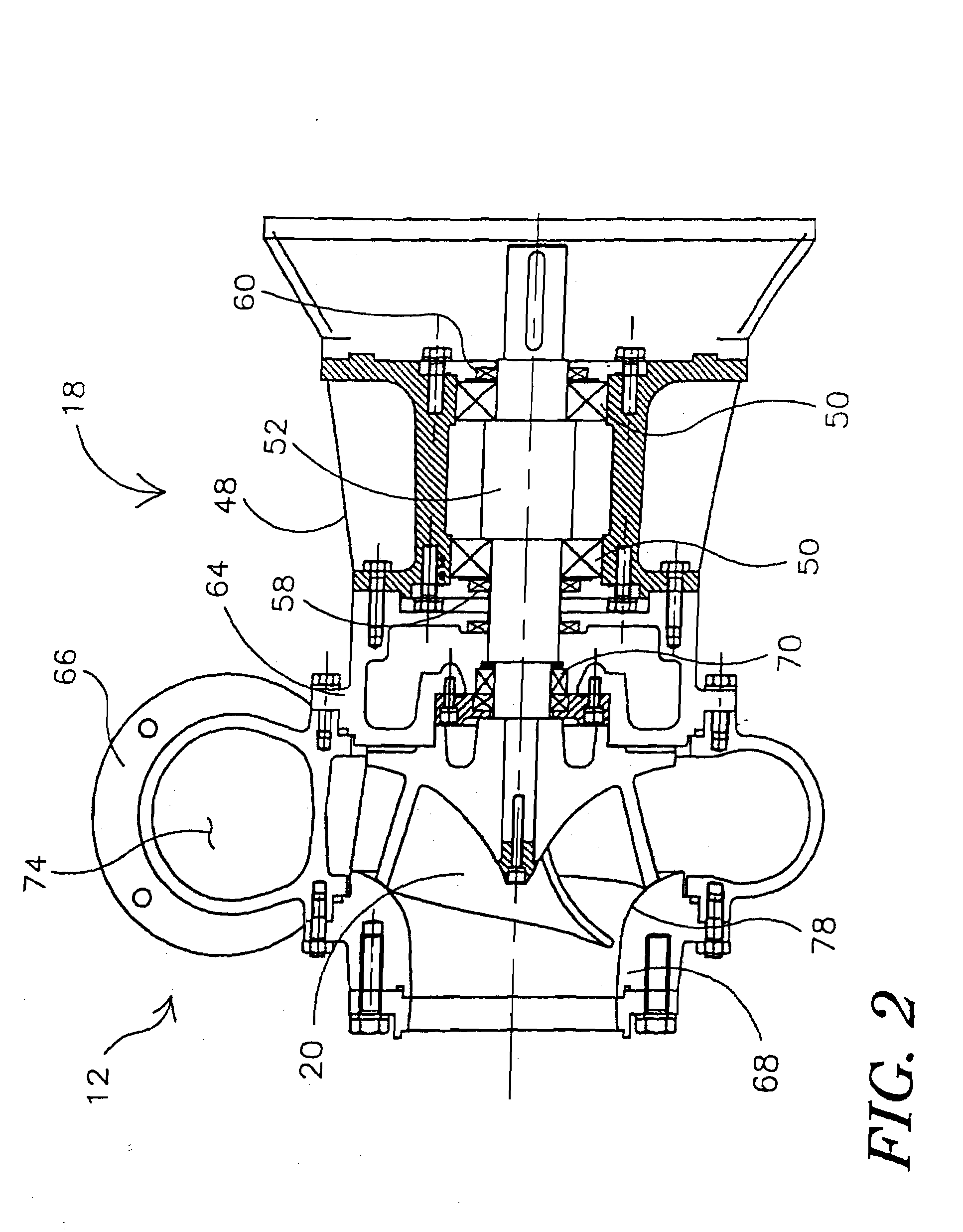
[0009] As noted above, the inner tank may receive liquid from the discharge of the vacuum pump, and provides liquid to the liquid ring vacuum pump. To increase the reliability of the liquid ring vacuum pump, the inner tank may be designed to collect sediments in the liquid of the vacuum pump system. For example, the bottom and / or side surfaces of the inner tank may be configured to help collect sediment near a drain port. Alternatively, or in addition, one or more baffles may be provided to help direct or collect the sediment. Once the sediment is collected, a drain port can be opened, and the collected sediment may be removed. In-line filters may also be provided, to help further collect sediment.
[0010] Under some conditions, the fluid level in the inner tank may decrease over time. To help maintain a proper fluid level in the inner tank, it is contemplated that the inner tank may be selectively fluidly connected to a fluid source, such as the main pump output. When connected, the fluid source may provide fluid, preferably under pressure, to the inner tank to replenish the fluid in the inner tank. A filter may be provided between the fluid source and the inner tank to help prevent sediment from entering the inner tank.
[0011] Under positive head pressure, the fluid level in the reservoir will tend to rise, and in some circumstances, fill the reservoir. To help prevent the pumped fluid in the reservoir from escaping from the reservoir, it is contemplated that the valve that is controlled by the float in the reservoir may be a one-way valve, letting air into the reservoir when the fluid level rises above a desired fluid level, but not letting fluid out of the reservoir. In addition, a valve may be disposed between the upper outlet in the reservoir and the inlet of the vacuum pump. This valve may close when the fluid level in the reservoir reaches some predefined maximum level. Preferably, when the fluid level in the reservoir reaches the predefined maximum level, the valve between the upper outlet in the reservoir and the inlet of the vacuum pump fluidly connects the inlet of the vacuum pump to atmosphere. This may help reduce the load on the vacuum pump.

Problems solved by technology

It has been found that this airflow, along with vibration or movement of the pump, may cause the pumped fluid inside the reservoir to splash, mist, or otherwise enter the inlet of the vacuum pump.
This fluid, which may include sediments or the like, may cause damage to the vacuum pump.
In cold weather applications, the fluid may also dilute any antifreeze used in the vacuum pump system, which can reduce the reliability of the system.

Method used


Image

  • Pump system with vacuum source
  • Pump system with vacuum source
  • Pump system with vacuum source

Examples


Embodiment Construction

[0051] The following detailed description should be read with reference to the drawings, in which like elements in different drawings are numbered in like fashion. The drawings which are not necessarily to scale, depict selected embodiments and are not intended to limit the scope of the invention. In some cases, the drawings may be highly diagrammatic in nature. Examples of constructions, materials, dimensions, and manufacturing processes are provided for various elements. Those skilled in the art will recognize that many of the examples provided have suitable alternatives which may be utilized.

[0052] The present invention provides an improved pump assembly and related components. The improved pump assembly is generally shown in FIG. 1 and includes a separator 10, a centrifugal primary pump assembly 12, a liquid ring vacuum pump 14 and a motor 16.

[0053] The separator 10 includes an intake port 22 and an output port 24. The intake port 22 is the input port for the pump. The intake ...


PUM

PropertyMeasurementUnit
pressureaaaaaaaaaa
widthaaaaaaaaaa
widthaaaaaaaaaa

Abstract

A self priming pump system that includes a motor coupled to a centrifugal pump for driving the centrifugal pump. A separator having a reservoir is provided for storing a limited amount of pumped fluid in advance of the centrifugal pump. A vacuum source provides a vacuum suction to the reservoir to draw pumped fluid into the reservoir to prime the pump. To increase the reliability of the vacuum pump system, a deflector and / or extension may be provided in the reservoir to help prevent pumped fluid from entering the vacuum pump input. Also, the configuration of a tank used to store liquid for the vacuum pump system may be configured to separate and collect sediments near a drain port, which then can be easily drained. For positive head pressures, one or more valves may be used to prevent pumped fluid from escaping the reservoir, if desired.

Description

[0001] This application is a continuation of co-pending U.S. patent application Ser. No. 10 / 732,769, filed Dec. 10, 2003, entitled “Pump System With Vacuum Source,” which is a continuation of U.S. patent application Ser. No. 10 / 099,810, filed Mar. 15, 2002, entitled “Pump System With Vacuum Source” which is a continuation-in-part of U.S. patent application Ser. No. 09 / 907,193, filed Jul. 17, 2001, entitled “Pump System with Vacuum Source” which is a Divisional patent application Ser. No. 09 / 531,631 filed on Mar. 21, 2000, entitled “Pump System with Vacuum Source” which claims priority under 35 U.S.C. § 119(e)(1) to U.S. Provisional Patent Application Ser. No. 60 / 125,559, filed May 22, 1999, and entitled “Pump Assembly and Related Components”.FIELD OF THE INVENTION [0002] The present invention relates generally to pumps. More particularly, the present invention relates to self-priming pump systems. BACKGROUND OF THE INVENTION [0003] Self-priming pump systems typically include a motor...

Claims


Application Information

Patent Timeline
Patent Type & Authority Applications(United States)
IPC IPC(8): F04C19/00B01D21/00B60P3/22B67D7/74E03F1/00F04D7/04F04D9/04F04D13/02F04D29/22F04D29/70
CPCB01D21/0012B01D21/0018B01D21/0042B60P3/225E03F1/006F04C11/005F04C19/001F04C29/0092F04D7/04F04D7/045F04D9/041F04D9/042F04D13/02F04D29/2288F04D29/708B01D21/0039Y10T137/86043Y10T137/6416
Inventor MUHS, DAVID
Owner MULTIQUIP
Why Eureka
Try Eureka