
Fuel cell and cell fastening pins

Inactive Publication Date: 2006-05-25
HONDA MOTOR CO LTD
View PDF8 Cites 9 Cited by
  • Summary
  • Abstract
  • Description
  • Claims
  • Application Information

AI Technical Summary

Benefits of technology

[0010] In light of the above circumstances, an object of the present invention is to provide a fuel cell having a fastening structure enabling weight saving of the fuel cell and easy fastening operation, and to provide a cell fastening pin used for fastening the elements of each unit cell.
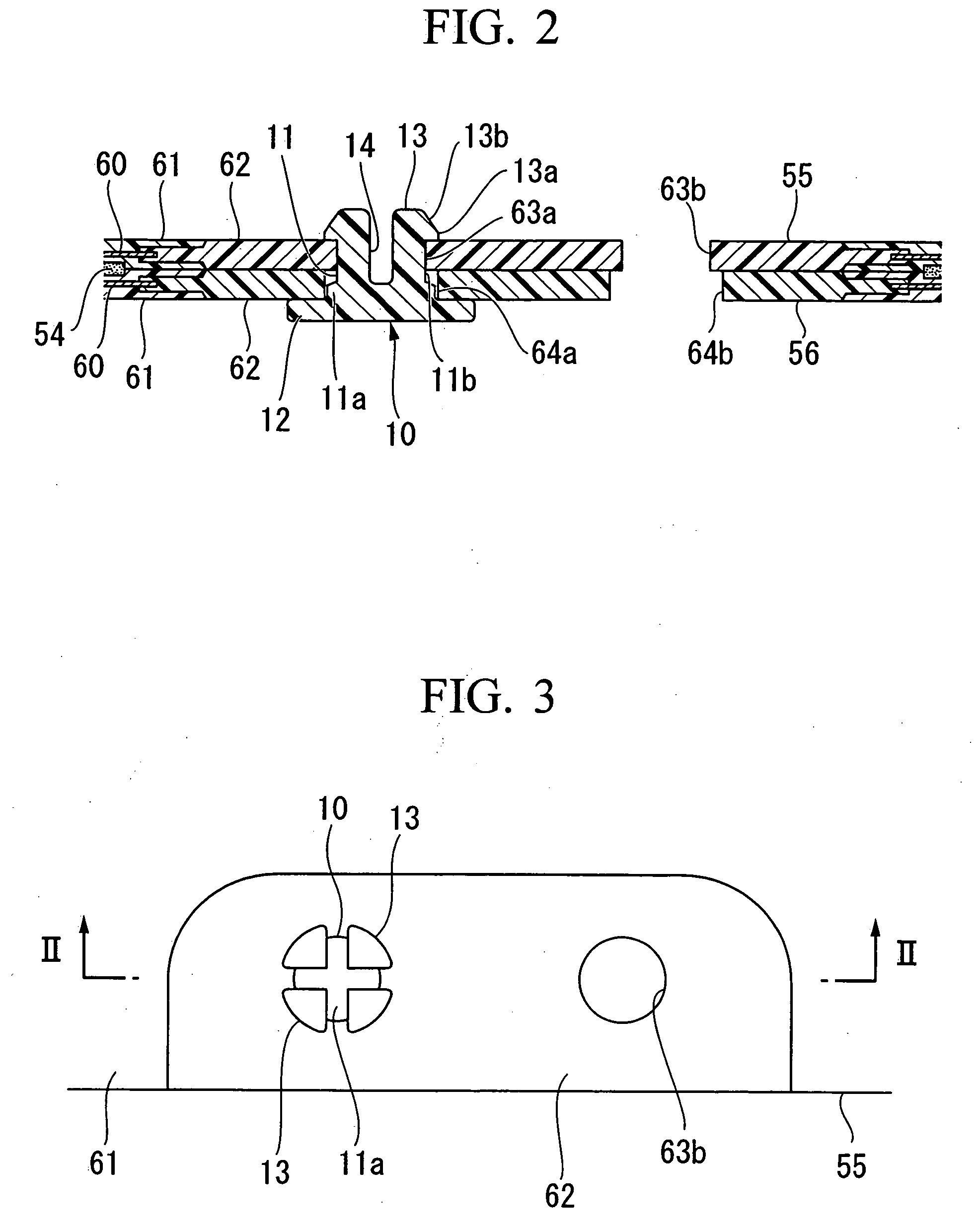
[0016] According to the above structure, the first and the second separators and the membrane electrode assembly can be fastened by the cell fastening pins made of resin, thereby reducing the weight of the fuel cell.
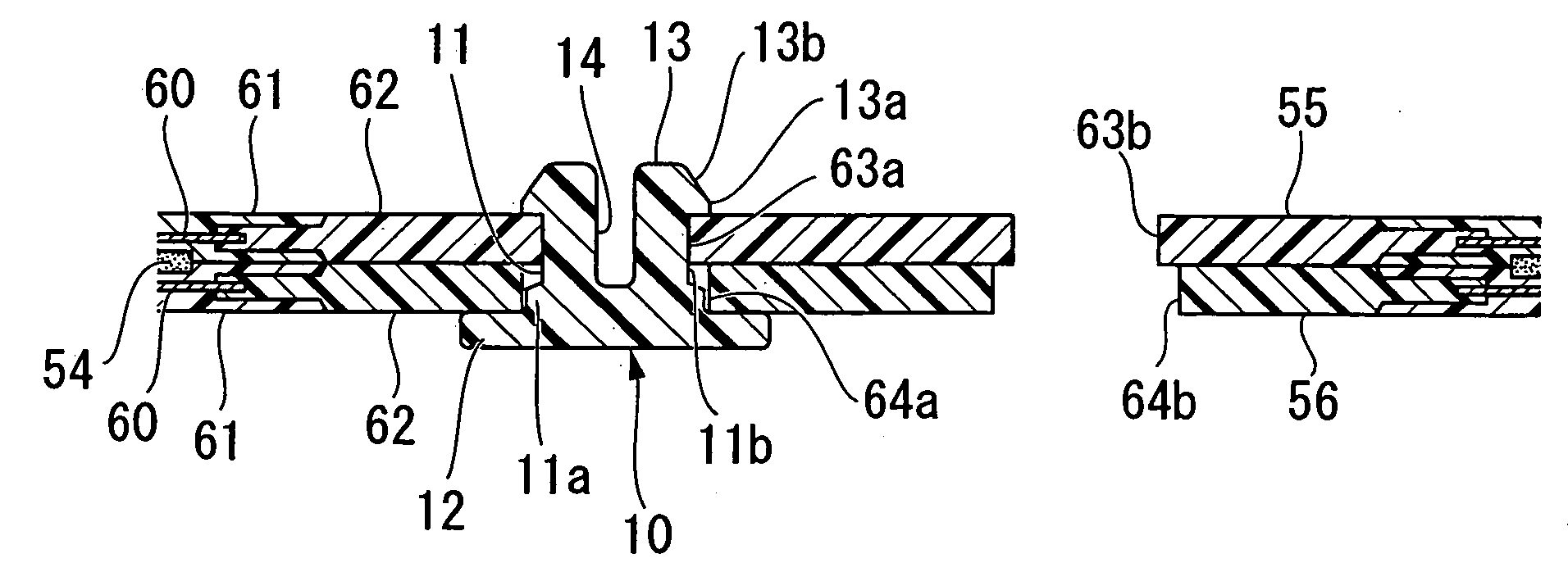
[0021] According to this structure, a head portion of each cell fastening pin of one of the stacked unit cells can enter the pin insertion hole of the first separator of the other unit cell; thus, it is possible to prevent the cell fastening pins of the one of the stacked unit cells from interfering with the other unit cell. In addition, the operator can easily distinguish the first separator and the second separator from each other at a glance by comparing the sizes of the pin insertion holes of the first and the second separators, thereby preventing an erroneous combination of the first and the second separators when forming the unit cell. Furthermore, each cell fastening pin is inserted from the corresponding pin insertion hole having a larger diameter of the first separator; thus, the pin insertion hole can guide the cell fastening pin, thereby improving working convenience.
[0025] According to the above structure, when the unit cells are stacked, the hook portion of each cell fastening pin, which protrudes from one of the unit cells, can enter the pin insertion hole at a corresponding position of the first separator of the other unit cell. Therefore, the length of the fuel cell in the stacking direction can be reduced, thereby reducing the size of the fuel cell. In addition, the first and the second separators of the fastened unit cell can be easily distinguished at a glance by comparing the sizes of the pin insertion holes where no cell fastening pin is mounted. Accordingly, when a plurality of the unit cells (each being fastened) are stacked, it is possible to reliably prevent an erroneous stacking state such that separators of the same electrode are adjacent to each other. Furthermore, each of the first and the second separators can be a common part for both unit cells. Accordingly, the kinds of parts can be reduced and the parts can be easily managed, thereby improving productivity.
[0030] According to the above structure, the cell fastening pin can be handled by grasping the handle, thereby improving handling performance in an operation of stacking the unit cells and improving productivity.
[0037] Accordingly, after the unit cell is fastened, each gate portion can be easily broken by a shearing force and only the cell fastening pin can remain in the unit cell.

Problems solved by technology

Therefore, this process is inconvenient and requires an additional cost, thereby increasing the manufacturing cost.
In addition, weight saving of elastic metal clips has a limit.
In particular, when tens to hundreds of unit cells are stacked so as to form a fuel cell stack, the total weight of the elastic clips is large, which prevents weight saving of the fuel cell stack.

Method used


Image

  • Fuel cell and cell fastening pins
  • Fuel cell and cell fastening pins
  • Fuel cell and cell fastening pins

Examples


Embodiment Construction

[0048] Hereinafter, embodiments of a fuel cell and a cell fastening pin according to the present invention will be described with reference to the appended figures (i.e., FIGS. 1 to 10).

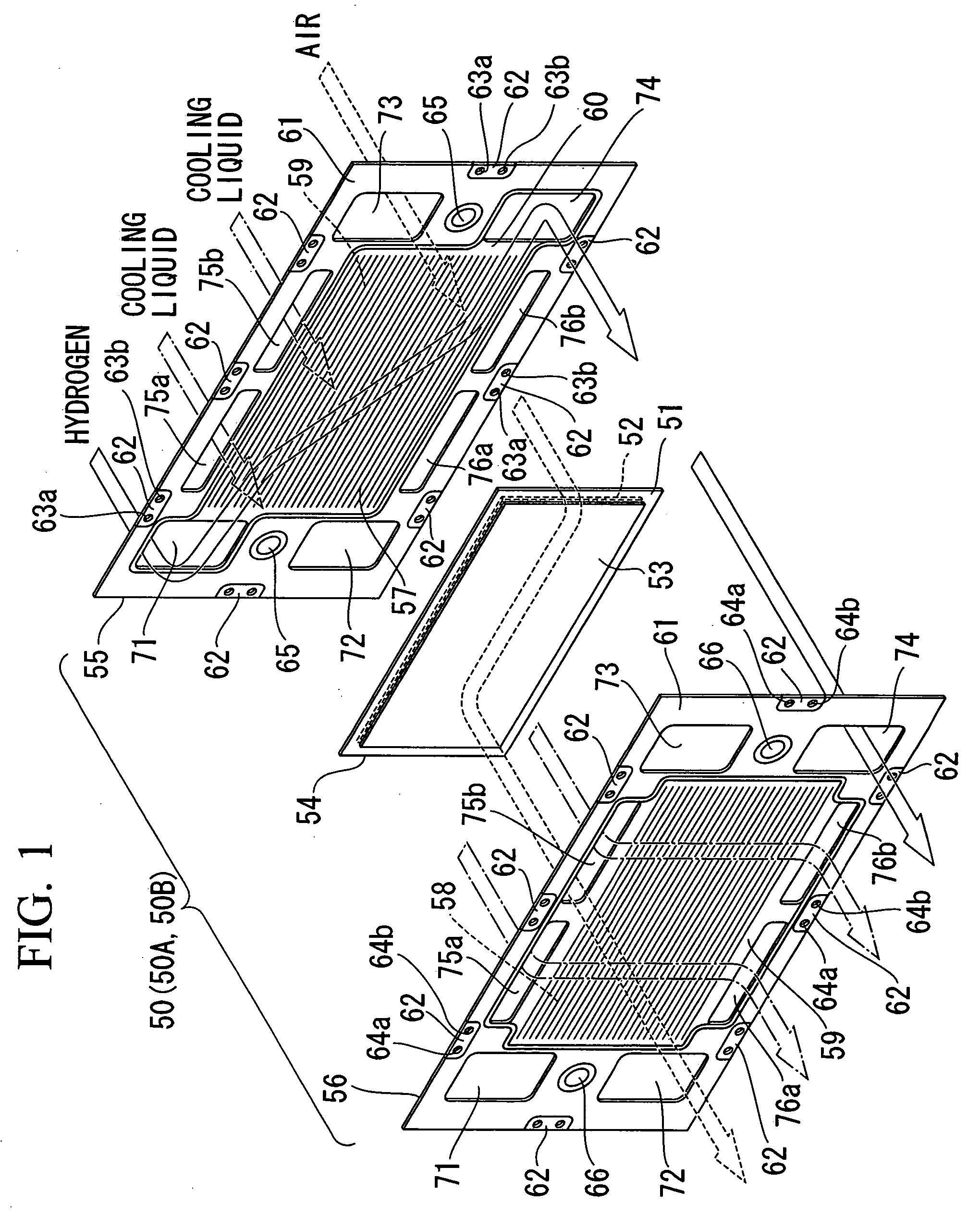
[0049]FIG. 1 is an exploded perspective view showing a unit cell of the fuel cell as an embodiment of the present invention. The fuel cell in the present embodiment is a solid polymer electrolyte membrane type. As shown in FIG. 1, an anode 52 (i.e., an electrode) and a cathode 53 (i.e., another electrode) are provided on either side of a solid polymer electrolyte membrane 51 (made of a fluorine electrolyte material or the like) so as to form a membrane electrode assembly 54. The membrane electrode assembly 54 is closely placed between an anode separator 55 (corresponding to a second separator in the present invention) and a cathode separator 56 (corresponding to a first separator in the present invention) so as to form a unit cell 50 (i.e., a unit fuel cell). A plurality of the unit cells 50 are sta...


PUM


Abstract

A fuel cell has a unit cell in which a membrane electrode assembly, in which a pair of electrodes are provided on either side of an electrolyte membrane, is provided between a first separator and a second separator. Pin insertion holes are respectively provided in a plurality of portions in an outer periphery of each of the first and the second separators, and the pin insertion holes of the first separators are respectively coaxial with those of the second separator. A leg portion of a cell fastening pin made of resin is inserted through each pair of the coaxial pin insertion holes of the first and the second separators. The unit cell is fastened by fitting a flange portion formed at an end of the leg portion to the first separator, and fitting a hook portion formed at the other end of the leg portion to the second separator.

Description

BACKGROUND OF THE INVENTION [0001] 1. Field of the Invention [0002] The present invention relates to a fuel cell and cell fastening pins for fastening elements of a unit cell which is a constituent of the fuel cell. [0003] Priority is claimed on Japanese Patent Application No. 2004-338974, filed Nov. 24, 2004, the content of which is incorporated herein by reference. [0004] 2. Description of the Related Art [0005] In a known fuel cell, an anode and a cathode are provided on either side of a solid polymer electrolyte membrane so as to form a membrane electrode assembly. The membrane electrode assembly is placed between separators which are provided so as to form a unit cell. Generally, a specific number of unit cells are stacked to form a fuel cell stack. [0006] In consideration of easy handling, working convenience, productivity, or the like for the above kind of fuel cell, in each unit cell, the membrane electrode assembly and the separators on either side thereof may be fastened t...

Claims


Application Information

Patent Timeline
IPC IPC(8): H01M8/10H01M8/24A44B17/00A44B9/00
CPCF16B5/0642H01M8/0247H01M8/247Y10T24/3467H01M2008/1095Y02E60/50Y10T24/46H01M8/248
Inventor SAKANO, MASAAKISUGITA, NARUTOSHISUZUKI, RYUGO
Owner HONDA MOTOR CO LTD
Learn More