Position detection device, pointing device and input device

a technology of position detection and input device, which is applied in the direction of instruments, computing, electric digital data processing, etc., can solve the problems of increased production costs, increased production costs, and increased size of input device,

Inactive Publication Date: 2006-06-01
FUJITSU COMPONENENT LTD
View PDF21 Cites 17 Cited by
  • Summary
  • Abstract
  • Description
  • Claims
  • Application Information

AI Technical Summary

Benefits of technology

[0017] In accordance with the present invention, the friction generator, which generates a frictional force retaining the movable object at a fixed position of the retaining member. It is possible to control the movement of the movable object, even while the operator is not operati

Problems solved by technology

Therefore, there is a problem in that the production costs increase because of its complex structure around the electromagnetic conversion element.
If the size of the ball is reduced in order to downsize the input device, the input device is difficult to operate.
And, the structure is complicated and grows in size.
This arises a problem that an operational feeling gets worse and the interconnection to the switch is easy to be cut off, becaus

Method used


Image

  • Position detection device, pointing device and input device
  • Position detection device, pointing device and input device
  • Position detection device, pointing device and input device

Examples


first embodiment

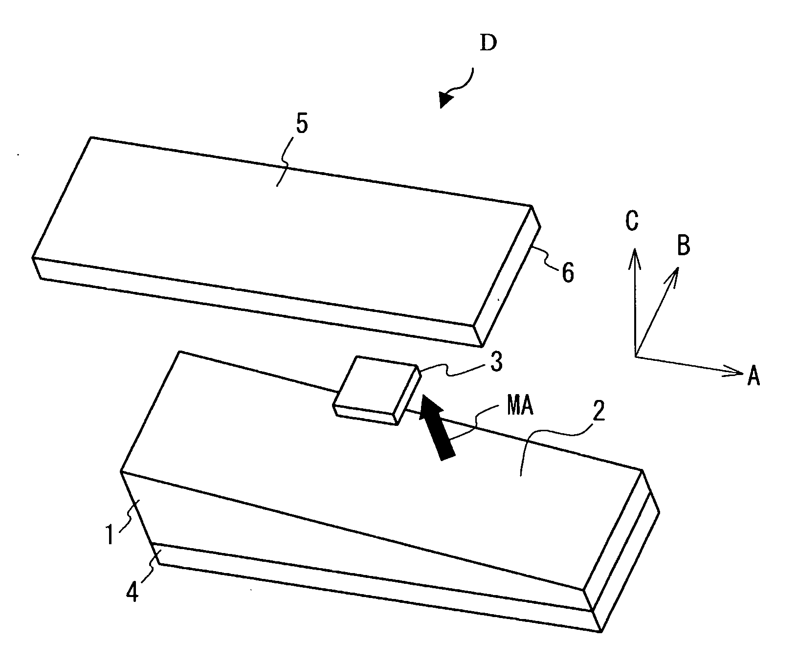
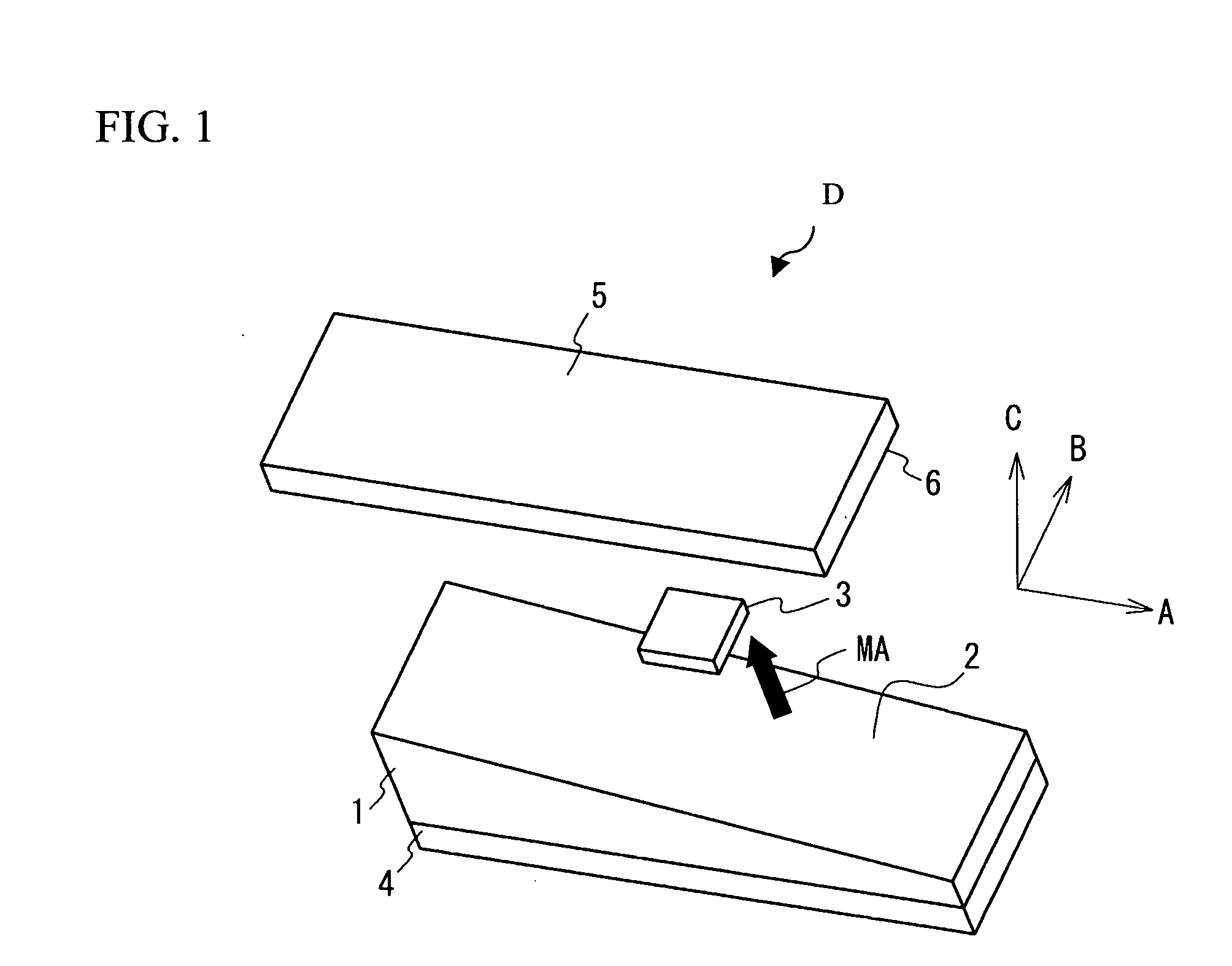
[0059]FIG. 1 illustrates an enlarged view of a sensor portion D, which is a principle portion of a position detection device. The sensor portion D has at least a magnet 1 serving as a magnetic field generator and an electromagnetic conversion element 3. The electromagnetic conversion element is arranged on a given plane. As is shown in FIG. 1, if three axes A, B and C are provided to be virtually crossed at right angles to each other, the electromagnetic conversion element 3 is arranged, for example, on an A-B plane at a given level in a C-axis direction. The magnet 1 is arranged to face one side of the electromagnetic conversion element 3 in a direction vertical to the A-B plane. A face 2 (hereinafter referred to an opposed face 2) at one side of the magnet 1 facing the electromagnetic conversion element 3 is a plane tilting linearly. Specifically, the magnet 1 has a rectangular shape, when it is projected on the A-B plane, and the magnet 1 is arranged in such a manner that a longe...

second embodiment

[0073] In the sensor portion D of the position detection device in accordance with a second embodiment of the present invention, the opposed face 2 of the magnet 1 facing the electromagnetic conversion element 3 has another shape. FIG. 6A through 6D illustrate the sensor portion D of the position detection device in accordance with the second embodiment. FIG. 6A through FIG. 6D show illustrative variations of the opposed face 2 of the magnet 1. Although the opposed face 2 of the magnet 1 in accordance with the first embodiment has a plate shape tilting linearly in a direction of the relative displacement of the magnet 1 and the electromagnetic conversion element 3, the opposed face in accordance with the second embodiment has a curved surface. A magnetic field disturbance might exist at the position where the electromagnetic conversion element 3 is arranged. As is shown in FIG. 6, it is possible to correct the output of the electromagnetic conversion element 3 to be linearized by cu...

third embodiment

[0077] In the first embodiment and the second embodiment mentioned above, the opposed face 2 tilts based on the changing thickness of the magnet 1. In the sensor portion D of the position detection device in accordance with a third embodiment, the opposed face 2 is made to tilt by changing the thickness of the first yoke 4 provided under the magnet 1. FIG. 7A through FIG. 7E illustrate the sensor portion D included in the position detection device in accordance with the third embodiment. FIG. 7A through FIG. 7E show illustrative variations in which the opposed face 2 tilts based on the changing thickness of the yoke 4, and then the shape of the opposed face 2 is changed.

[0078] The structure example shown in FIG. 7A corresponds to the structure in accordance with the first embodiment. The thickness of the first yoke 4 changes in parallel with the relative displacement direction MU of the magnet 1 and the electromagnetic conversion element 3. Accordingly, the opposed face 2 having a ...


PUM


Abstract

A position detection device includes an electromagnetic conversion element and a magnetic field generator. The electromagnetic conversion element is arranged on a given plane. The magnetic field generator is arranged facing one side of the electromagnetic conversion element in a direction vertical to the given plane and generates a magnetic field covering the electromagnetic conversion element. A relative position between the electromagnetic conversion element and the magnetic field generator is detected when a relative displacement parallel to the given plane is made by the electromagnetic conversion element and the magnetic field generator based on an output signal of the electromagnetic conversion element. The magnetic field generator has an opposed face that tilts to the electromagnetic conversion element, and generates the magnetic field from the opposed face.

Description

BACKGROUND OF THE INVENTION [0001] 1. Field of the Invention [0002] This invention generally relates to a non-contact position detection device, and in particular, relates to a device which detects a position by detecting a magnetic field generated from a magnet with an electromagnetic conversion element. In addition, this invention generally relates to a pointing device which is connected to an information processing apparatus such as a personal computer, a PDA, a cellular phone, a navigation system or the like to be used when position information or direction information are input, and in particular, relates to a pointing device which is capable of determining or settling an input. Further, this invention relates to an input device used to input an instruction into a personal computer or the like, and in particular, relates to an input device having a structure in which an operation portion operated by an operator during an operation is retained stably. [0003] 2. Description of th...

Claims


Application Information

Patent Timeline
IPC IPC(8): G09G5/00
CPCG06F3/0354
Inventor SAKURAI, SATOSHIYATSU, NOBUOAKIEDA, SHINICHIROSHIMIZU, NOBUYOSHIHARADA, KEITA
Owner FUJITSU COMPONENENT LTD
Why Eureka
Try Eureka