
Liquid crystal panel and liquid crystal display apparatus

a liquid crystal display and liquid crystal technology, applied in the field of liquid crystal panels, can solve the problems of reducing the contrast ratio, increasing the display color varying phenomenon (also referred to as color shift), and not improving the contrast ratio in an oblique direction. , to achieve the effect of reducing the color shift and increasing the contrast ratio

Active Publication Date: 2006-06-01
NITTO DENKO CORP
View PDF18 Cites 50 Cited by
  • Summary
  • Abstract
  • Description
  • Claims
  • Application Information

AI Technical Summary

Benefits of technology

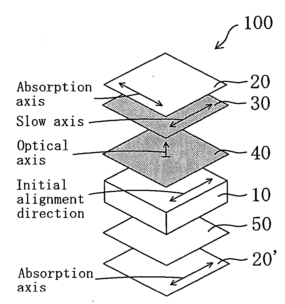
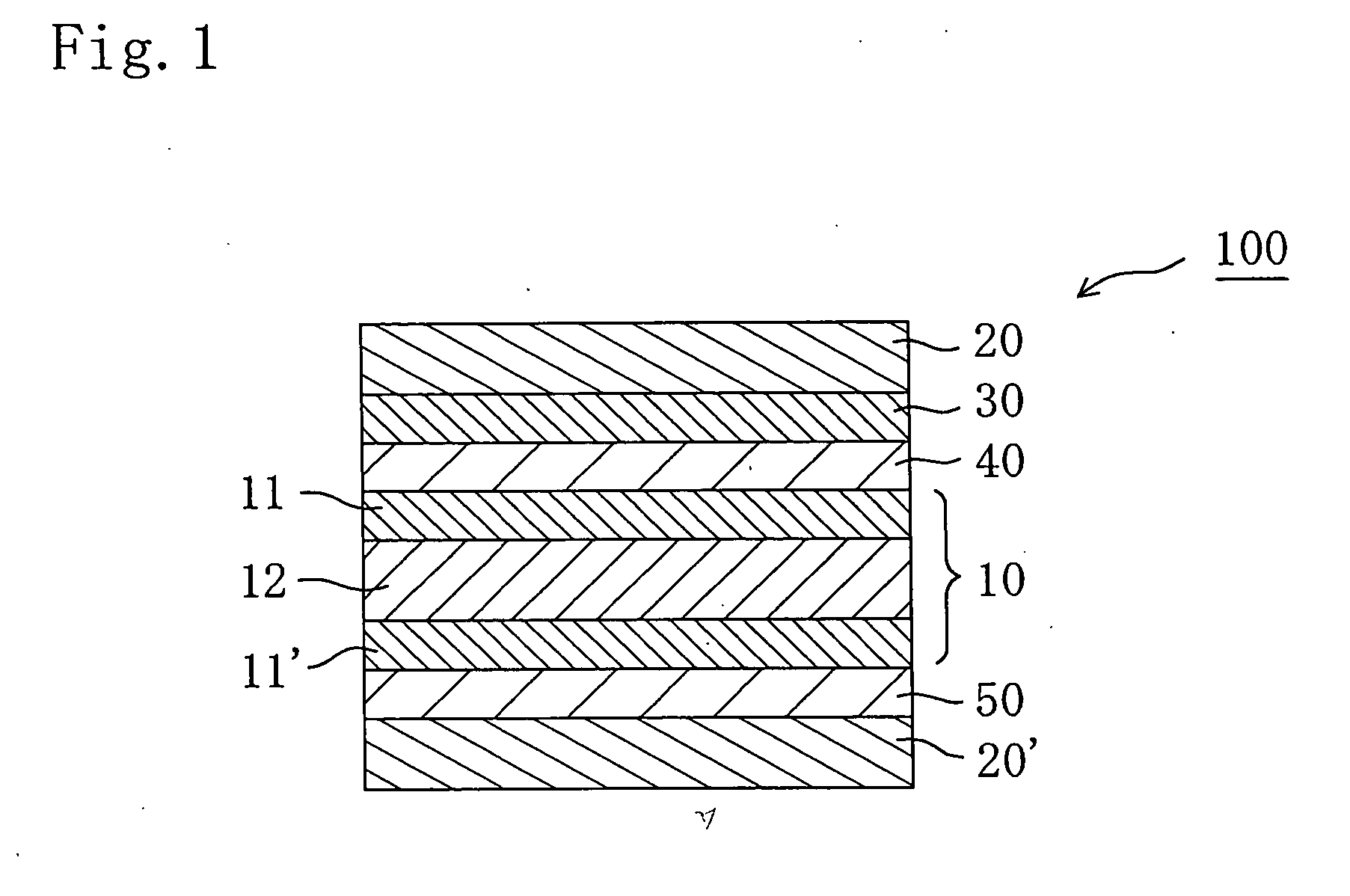
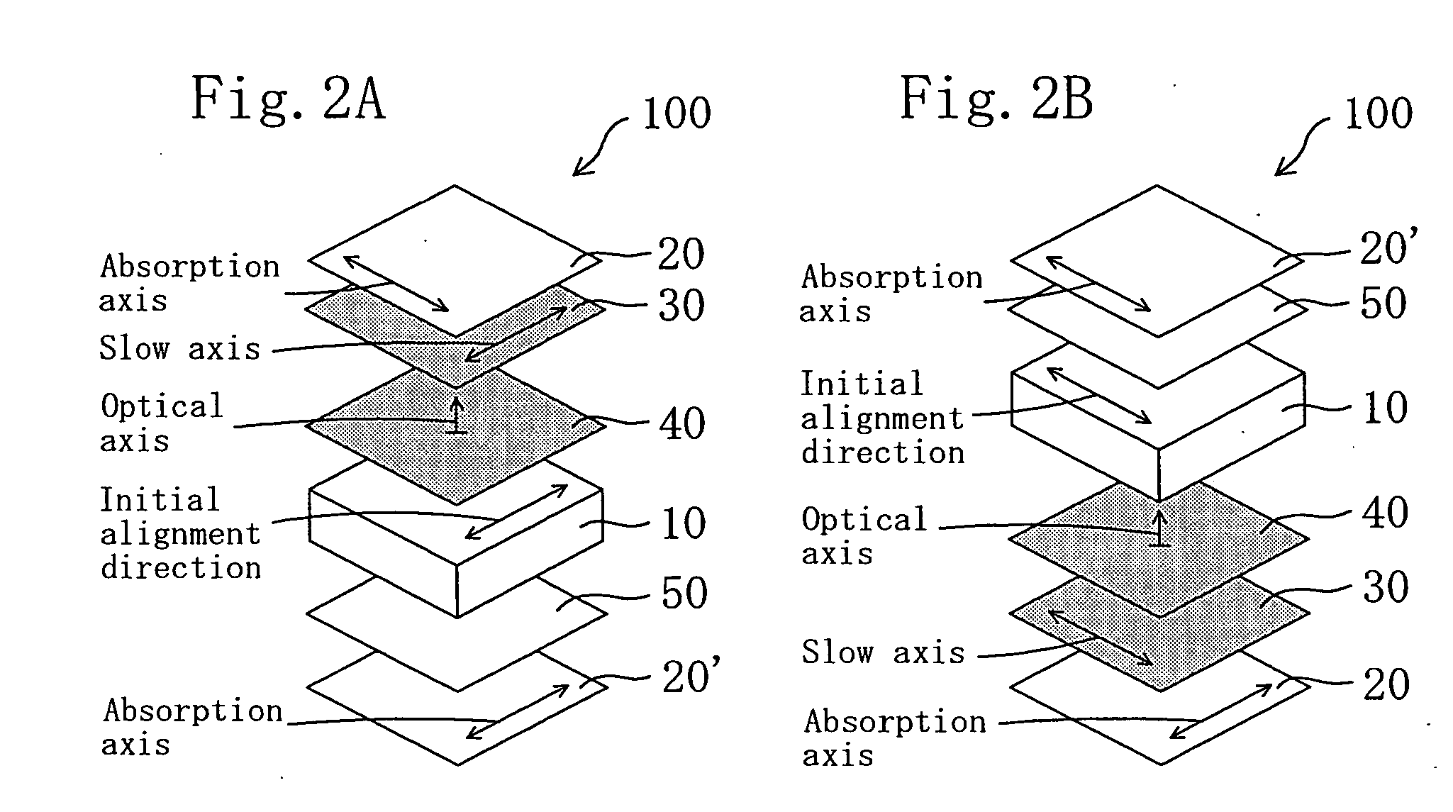
The present invention provides a liquid crystal panel with improved contrast ratio and color shift in an oblique direction. This is achieved by a specific arrangement of optical elements including a negative biaxial optical element and a positive C plate between the liquid crystal cell and the polarizers. The negative biaxial optical element is arranged between the first polarizer and the positive C plate, and the isotropic optical element is arranged between the liquid crystal cell and the second polarizer. This arrangement improves the contrast ratio and reduces color shift in the oblique direction of the liquid crystal display apparatus.

Problems solved by technology

A conventional liquid crystal display apparatus provided with a liquid crystal cell of IPS mode has problems in that: a contrast ratio is reduced when a screen is viewed from an oblique direction at an angle of 45° (azimuth angle of 45°, 135°, 225°, or 315°) with respect to an absorption axis of a polarizing plate; and a display color varying phenomenon (also referred to as color shift) increases depending on an angle the screen is viewed.
Thus, there is disclosed a method of improving a color shift by arranging a plurality of retardation films on one side of a liquid crystal cell (see JP 11-133408, for example) However, such a technique improves the color shift, but does not sufficiently improve the contrast ratio in an oblique direction.

Method used


Image

  • Liquid crystal panel and liquid crystal display apparatus
  • Liquid crystal panel and liquid crystal display apparatus
  • Liquid crystal panel and liquid crystal display apparatus

Examples


reference example 1

[0173] A commercially available polymer film “KC12UR” (trade name, thickness of 120 μm, available from Konica Minolta Holdings, Inc.) containing a cellulose ester as-a main component was longitudinally uniaxially stretched 1.30 times in an air-circulating thermostatic oven at 150° C. (temperature measured at a distance of 3 cm from a back surface of the film, temperature fluctuation of ±1° C.) by using a roll stretching machine while a longitudinal direction of the film was held, to thereby produce a retardation film A. Table 1 shows properties of the obtained retardation film A. The polymer film (before stretching) had Re[590] of 12 nm and Rth[590] of 113 rim.

reference example 2

[0174] A polymer film (thickness of 160 μm) was formed through solvent casting by using a cellulose ester (prepared in accordance with Example 1 of JP 2001-188128 A) containing as a main component a mixed organic acid ester having a degree of acetyl substitution of 2.0 and a degree of propionyl substitution of 0.8 in which hydroxyl groups of cellulose are substituted partly by an acetyl group and partly by a propionyl group. The polymer film was longitudinally uniaxially stretched 1.15 times in an air-circulating thermostatic oven at 150° C. (temperature measured at a distance of 3 cm from a back surface of the film, temperature fluctuation of ±1° C.) by using a roll stretching machine while a longitudinal direction of the film was held, to thereby produce a retardation film B. Table 1 shows the properties of the obtained retardation film B. The polymer film (before stretching) had Re[590] of 12 nm and Rth[590] of 113 nm.

reference example 3

[0175] A commercially available polymer film “ZEONOR ZF14-060” (trade name, thickness of 60 μm, glass transition temperature of 136° C., available from Zeon Corporation) containing polynorbornene as a main component was transversely uniaxially stretched 1.8 times in a width direction in an air-circulating thermostatic oven at 140° C. (temperature measured at a distance of 3 cm from a back surface of the film, temperature fluctuation of ±1° C.) by using a tenter stretching machine while a longitudinal direction of the film was held, to thereby produce a retardation film C. Table 1 shows the properties of the obtained retardation film C. The polymer film (before stretching) had Re[590] of 2.7 nm and Rth[590] of 0.5 nm.

Production of Positive C Plate


PUM

PropertyMeasurementUnit
thickness direction retardation valueaaaaaaaaaa
thickness direction retardationaaaaaaaaaa

Abstract

A liquid crystal panel according to an embodiment of the present invention includes: a liquid crystal cell; a first polarizer arranged on one side of the liquid crystal cell; a second polarizer arranged on another side of the liquid crystal cell; a negative biaxial optical element and a positive C plate arranged between the liquid crystal cell and the first polarizer; and an isotropic optical element arranged between the liquid crystal cell and the second polarizer. Here, the negative biaxial optical element is arranged between the first polarizer and the positive C plate.

Description

[0001] This application claims priority under 35 U.S.C. Section 119 to Japanese Patent Application No. 2004-344053 filed on Nov. 29, 2004 and Japanese Patent Application No. 2005-244847 filed on Aug. 25, 2005, which are herein incorporated by reference. FIELD OF THE INVENTION [0002] The present invention relates to a liquid crystal panel having a liquid crystal cell, a polarizer, and an optical element. Further, the present invention relates to a liquid crystal television and a liquid crystal display apparatus both using the liquid crystal panel. DESCRIPTION OF THE RELATED ART [0003] A liquid crystal display apparatus provided with a liquid crystal cell of in-plane switching (IPS) mode involves control of light transmittance (white display) and light shielding (black display) through applying an electric field in a horizontal direction on liquid crystal molecules aligned in a substantially horizontal direction without application of the electric field to rotate the liquid crystal mo...

Claims


Application Information

Patent Timeline
Patent Type & Authority Applications(United States)
IPC IPC(8): G02F1/1335G02B5/30G02F1/13363G02F1/139
CPCG02B5/3016G02F1/1335G02F1/133634G02F1/134363G02F1/141G02F2001/133531G02F2201/50G02F1/133531G02B5/30G02F1/13363
Inventor KOBAYASHI, KENTAROUYANO, SHUUJIKOISHI, NAOKI
Owner NITTO DENKO CORP
Learn More