Orthogonal frequency division demodulator, method and computer program product

a demodulator and orthogonal frequency technology, applied in the field of orthogonal frequency division multiplexing demodulators, can solve problems such as deterioration of reception characteristics

Inactive Publication Date: 2006-06-01
KK TOSHIBA
View PDF9 Cites 27 Cited by
  • Summary
  • Abstract
  • Description
  • Claims
  • Application Information

AI Technical Summary

Benefits of technology

[0006] Accordingly, an advantage of an aspect of the present invention is to provide an OFDM demodulator providing improved reception characteristics in the case where the level of a delay difference greater than the GI is large.
[0009] According to another embodiment of the present invention there is provided a novel computer program product storing a program which, when executed by a processor in an apparatus configured to demodulate an OFDM received signal including plural delayed signals received by an antenna, causes the processor to perform steps including estimating a channel response based on the received signal, and controlling a length of a retention interval based on the estimated channel response. The retention interval includes a time period between a first time when a head of a delayed signal having a maximum delay difference among the delayed signals is received and a second time when a tail of a preceding signal included in the received signal is received. The method also includes retaining a portion of the received signal corresponding to the retention interval, generating OFDM symbol candidates, converting the OFDM symbol candidates into time domain signals, generating replica signals of the received signal based on the time domain signals and the estimated channel response, calculating likelihoods that the replica signals are equivalent to the portion of the received signal retained in the retention memory, and selecting an OFDM symbol from the OFDM symbol candidates that corresponds to the replica signal having a maximum likelihood.

Problems solved by technology

Such an equalizer, however, has a problem that reception characteristics deteriorate as the level of delay difference greater than the GI increases.

Method used


Image

  • Orthogonal frequency division demodulator, method and computer program product
  • Orthogonal frequency division demodulator, method and computer program product
  • Orthogonal frequency division demodulator, method and computer program product

Examples


first embodiment

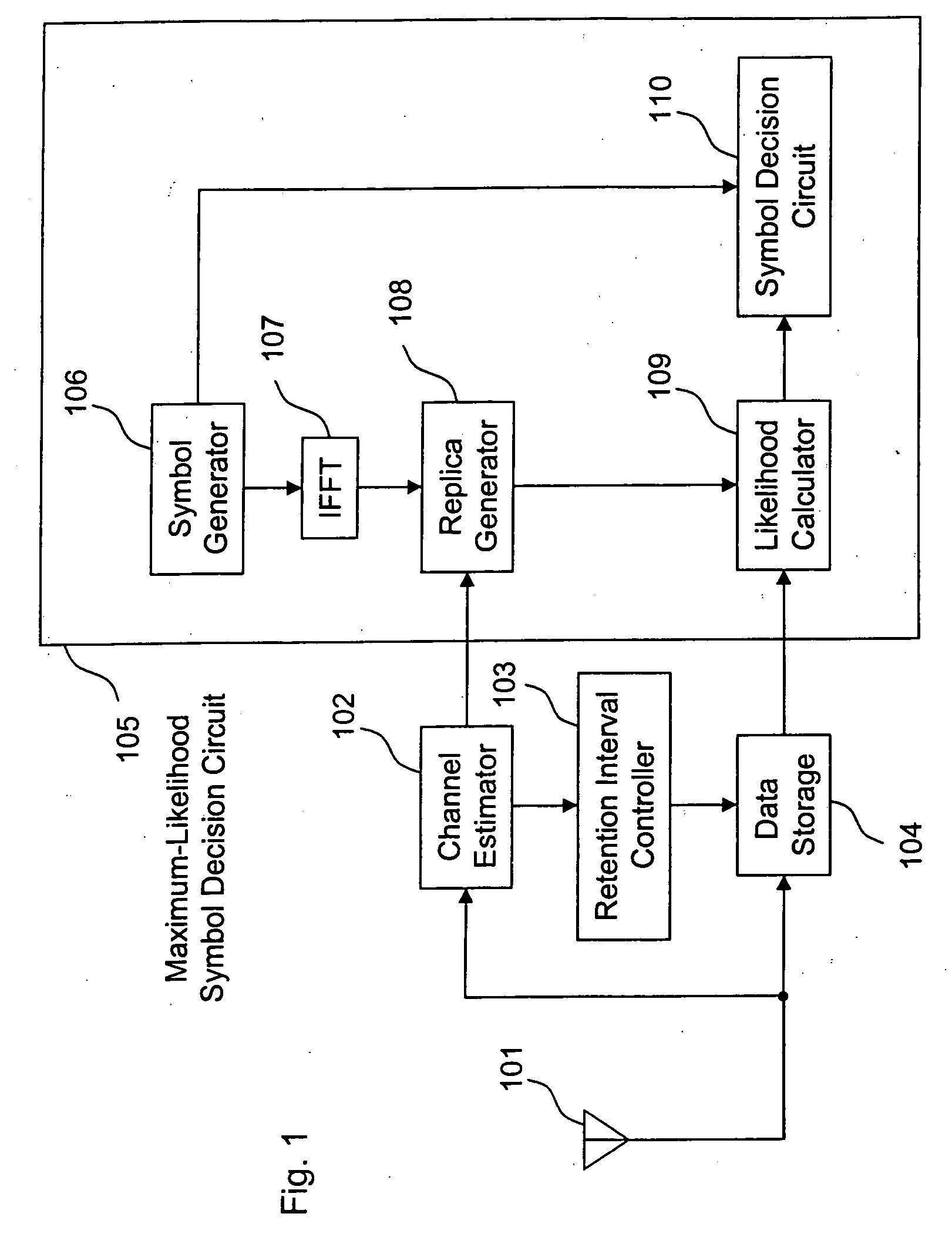
[0047]FIG. 1 is a block diagram of an OFDM demodulator according to a first embodiment that includes an antenna 101, a channel estimator 102, a retention interval controller 103, a data storage 104 and a maximum-likelihood symbol decision circuit 105. The maximum-likelihood symbol decision circuit 105 includes a symbol generator 106, an IFFT (inverse fast Fourier transformer) 107, a replica generator 108, a likelihood calculator 109 and a symbol decision circuit 110.

[0048] The antenna 101 receives an OFDM signal and delivers the received signal to an LNA (low noise amplifier). The LNA amplifies the OFDM signal to a desired amplitude. A frequency converter converts the OFDM signal amplified by the LNA, into an IF (intermediate frequency) band. A variable-gain amplifier adjusts the frequency-converted OFDM signal to an appropriate signal level. An orthogonal demodulator subjects the level-adjusted OFDM signal to an orthogonal demodulation into a baseband signal. An A / D converter conv...

second embodiment

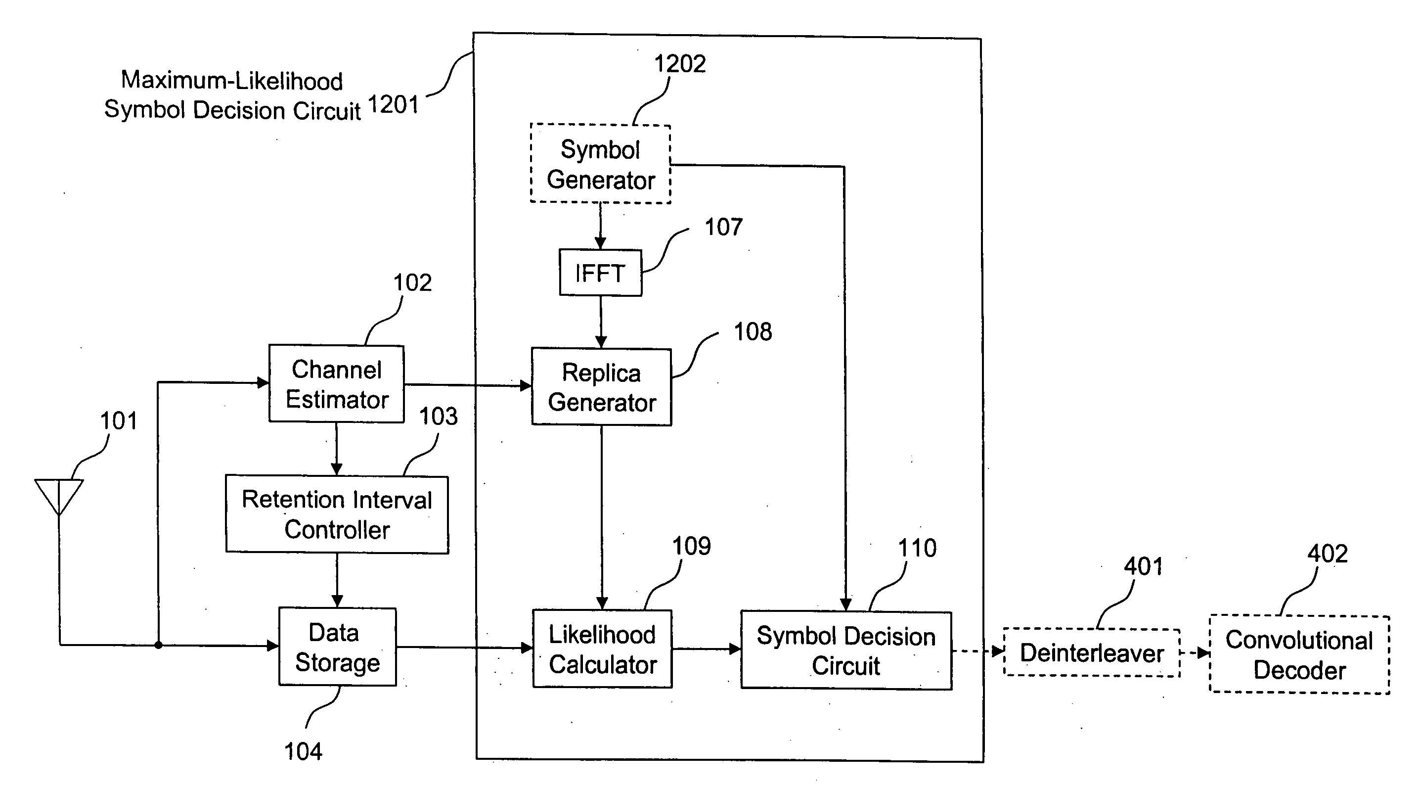
[0065]FIG. 4 is a block diagram of a second embodiment that corresponds to a case of performing error correction decoding. An OFDM demodulator according to the second embodiment extinguishes the data of subcarriers in accordance with the correctability of the error correction decoding to decrease the number of symbol candidates. Identical reference numerals are assigned to the same apparatus parts as in the OFDM demodulator of the first embodiment and these parts are omitted from following description.

[0066] As shown in FIG. 4, the OFDM demodulator of the second embodiment includes a deinterleaver 401 and a convolutional decoder 402 in addition to the parts of the OFDM demodulator of the first embodiment.

[0067] The deinterleaver 401 deinterleaves a symbol selected by a maximum-likelihood symbol decision circuit 105. The convolutional decoder 402 subjects the deinterleaved signal to convolutional decoding. The convolutional decoding is one of the error correction decoding technique...

third embodiment

[0070]FIG. 6 is a block diagram of a third embodiment that extinguishes data of subcarriers in accordance with a modulation scheme and error correction coding rate of a carrier to decrease a number of symbol candidates. Identical reference numerals are assigned to the same apparatus parts as in the OFDM demodulators of the first and second embodiments and these parts are omitted from the following description.

[0071] As shown in FIG. 6, the OFDM demodulator of this embodiment includes a transmission information detector 603.

[0072] A maximum-likelihood symbol decision circuit 601 sets some of the subcarriers to zero based on the modulation scheme and error correction coding rate (convolutional coding rate in this embodiment) of a carrier, generates a replica signal based on a channel response value from a channel estimator 102, and selects a symbol that maximizes the likelihood of the replica signal being equivalent to a digital signal stored in a data storage 104.

[0073] A symbol g...


PUM


Abstract

An OFDM demodulator that demodulates an OFDM signal includes an antenna that receives a signal including delayed signals, an estimation circuit that estimates the channel response of the received signal, and a control circuit that controls a length of a retention time interval based on the estimated channel response. The retention time interval includes a time period from the head of a delayed signal having a maximum delay time in the delayed signals to the tail of a preceding signal in the delayed signals based on the estimated channel response. The OFDM demodulator also includes a retention memory that retains a portion of the received signal corresponding to the retention time period, and a selection circuit that selects an OFDM symbol based on a calculation of a maximum likelihood that the retained received signal is equivalent to a signal replica based on the channel response.

Description

CROSS-REFERENCE TO RELATED APPLICATION [0001] This application is based upon and claims the benefit of priority from the prior Japanese Patent Application No. 2004-347777, filed Nov. 30, 2004, the entire contents of which are incorporated herein by reference. BACKGROUND OF THE INVENTION [0002] 1. Field of the Invention [0003] The present invention relates to an OFDM (Orthogonal Frequency Division Multiplexing) demodulator which demodulates an OFDM signal, and more particularly to an OFDM demodulator that reduces interference ascribable to a delay difference greater than the Guard Interval (GI). [0004] 2. Discussion of the Background [0005] A conventional countermeasure against having a delay difference greater than the GI includes an equalization that removes a delay difference greater than the GI. For example, Japanese Patent Application No. 2002-329715 describes a feedback type equalizer. Such an equalizer, however, has a problem that reception characteristics deteriorate as the l...

Claims


Application Information

Patent Timeline
Patent Type & Authority Applications(United States)
IPC IPC(8): H04J11/00
CPCH04L25/03006H04L2025/03414
Inventor KASAMI, HIDEOMATSUOKA, HIDEHIROTSURUTA, MAKOTO
Owner KK TOSHIBA
Why Eureka
Try Eureka