
Image processing apparatus and method

a technology of image processing and image, applied in the field of image processing apparatus and image processing method, can solve the problems of affecting the output image, affecting the operation of real-time performance, and causing so as to reduce the delay of the output image

Inactive Publication Date: 2006-06-01
SONY CORP
View PDF2 Cites 9 Cited by
  • Summary
  • Abstract
  • Description
  • Claims
  • Application Information

AI Technical Summary

Benefits of technology

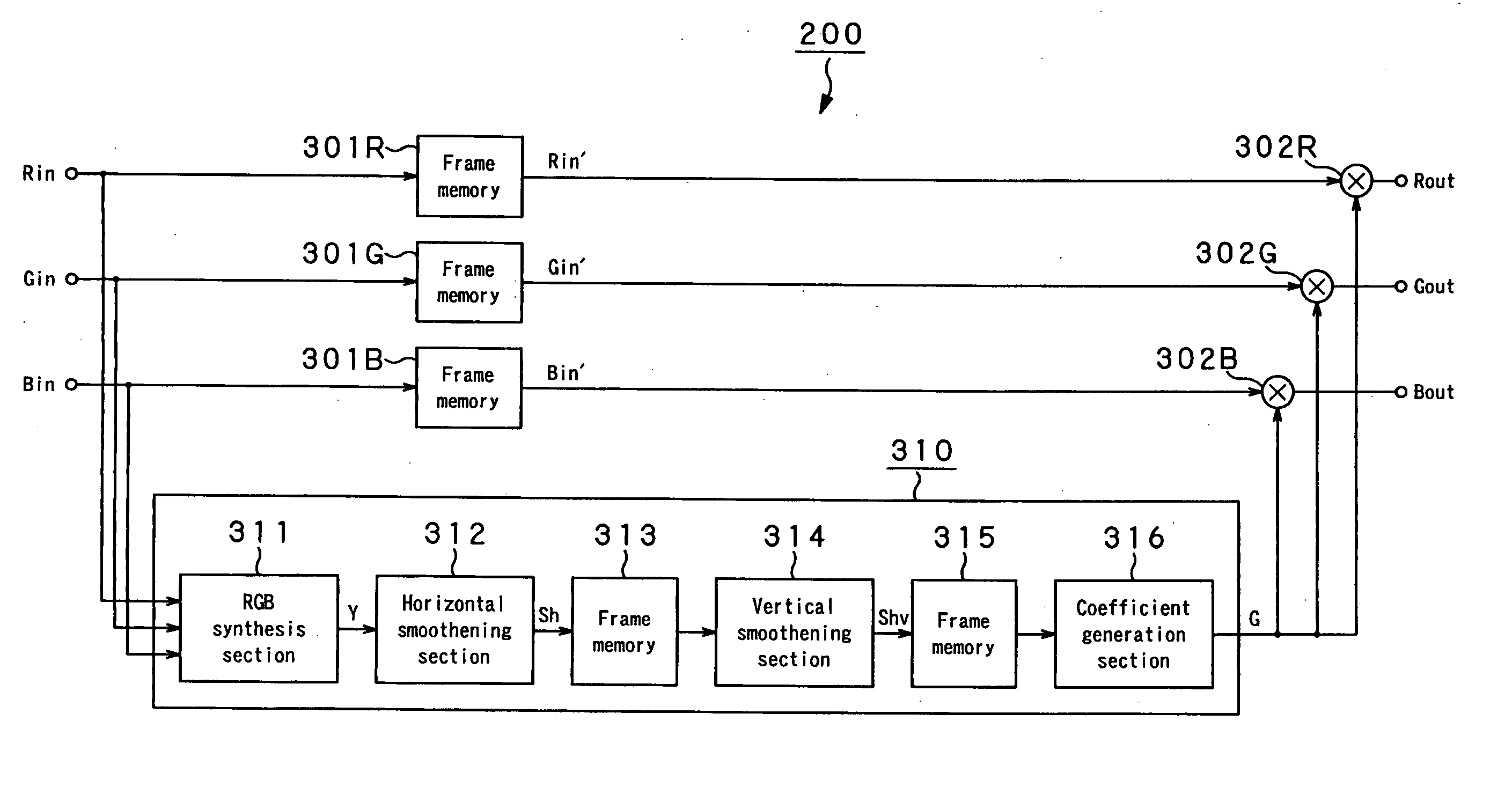
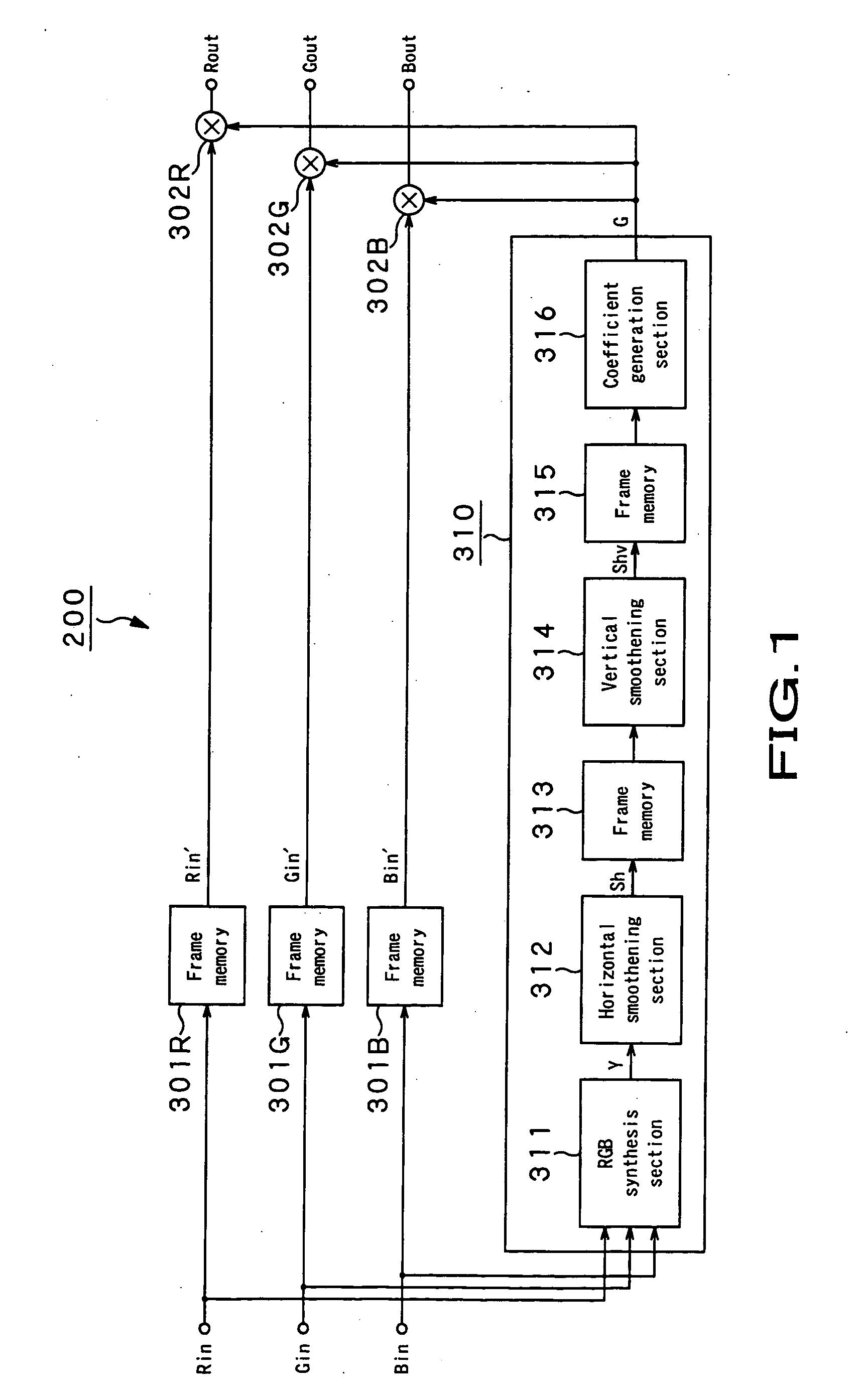
The present invention provides an image processing apparatus and method that reduces delay in outputting an image caused by filtering. The apparatus includes a non-linear smoothening means for smoothening image signals in horizontal and vertical directions while storing an edge component of the image signal. A mixing means is used to mix the non-linear smoothened image signal with the input image signal. A correction coefficient calculation means calculates a gain correction coefficient based on the mixture image signal, and a compression processing means compresses the dynamic range of the input image signal by multiplying it with the gain correction coefficient. The apparatus can also include a difference signal emphasis means for subjecting a difference between the mixture image signal and the input image signal to gradation conversion and adding it to the original image. The technical effect of the invention is to reduce delay in outputting an image while maintaining image quality.

Problems solved by technology

Therefore, in image processing apparatuses using these methods, a delay is caused by filtering through the large smoothening filter from the start to end of processing.
An image to be outputted comes with a relatively long delay.
This delay of an output image causes a problem that deterioration in following response leads to worse operationality in operations that requires real-time performance, such as focusing, tracking of a target object, and the like.

Method used


Image

  • Image processing apparatus and method
  • Image processing apparatus and method
  • Image processing apparatus and method

Examples


Embodiment Construction

[0040] Hereinafter, embodiments of the present invention will be described in details with reference to the drawings. Needless to say, the present invention is not limited to the following embodiments but is arbitrarily modifiable without deviating from the subject matter of the present invention.

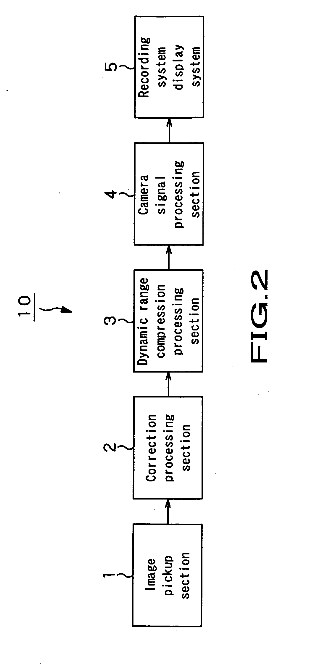
[0041] The present invention is applied to, for example, an image pickup device 10 having a structure as shown in FIG. 2.

[0042] The image pickup device 10 has: an image pickup section 1 which picks up and image of an object by a solid-state image pickup element such as a C-MOS image sensor, CCD (Charge Coupled Device) image sensor, or the like; a correction processing section 2 which is supplied with an image signal obtained as an image-pickup output signal by the image pickup section 1; a compression / emphasis processing section 3 which is supplied with an image signal subjected to a correction processing on a shading component by the correction processing section 2; and a camera signal p...


PUM


Abstract

The present invention reduces a delay of an output image which is originally caused by compression or emphasis processing when compressing the dynamic range of an image or emphasizing the contrast of an image, to obtain a processed-image output on real time. The present invention provides an image processing apparatus including a non-linear smoothening unit that non-linearly smoothens an input image signal in horizontal and vertical directions while storing an edge component of the input image signal whose signal level varies, a mixing unit that mixes the image signal non-linearly smoothened by the non-linear smoothening unit with the input image signal, a correction coefficient calculation unit that calculates a gain correction coefficient, based on a mixture image signal mixed by the mixing unit, and a compression processing unit that compresses a dynamic range of the input image signal by multiplying the input image signal by the gain correction coefficient calculated by the correction coefficient calculation unit.

Description

CROSS REFERENCES TO RELATED APPLICATIONS [0001] The present invention contains subject matter related to Japanese Patent Application JP 2004-344794 filed in the Japanese Patent Office on Nov. 29, 2004, the entire contents of which being incorporated herein by reference. BACKGROUND OF THE INVENTION [0002] 1. Field of the Invention [0003] The present invention relates to an image processing apparatus and an image processing method, and is applied to processing and recording of results of images picked up, for example, by a video camera, an electronic still camera or the like, image display by a liquid crystal display apparatus or the like, image processing and image synthesis by a personal computer or the like, and transfer of images by these devices. [0004] 2. Description of the Related Art [0005] In the past, in various image processing circuits for an image pickup device or the like, various processings such as recording, reproduction, and the like are executed, compressing the dyn...

Claims


Application Information

Patent Timeline
Patent Type & Authority Applications(United States)
IPC IPC(8): G06K9/00
CPCG06T5/009G06T5/50H04N5/142H04N5/20H04N9/69G06T5/92
Inventor TSUCHIYA, TAKASHI
Owner SONY CORP
Learn More