Method for controlling the properties of DARC and manufacturing DARC

a technology of anti-reflective coating and darc, which is applied in the direction of photomechanical treatment, instruments, electrical equipment, etc., can solve the problems of high accuracy of transfer pattern after photolithographic process, high difficulty in photolithographic process, and error during photolithographic process, so as to reduce the difference in the reflectivity of darc covering the pattern at different height levels

Active Publication Date: 2006-06-01
MACRONIX INT CO LTD
View PDF0 Cites 0 Cited by
  • Summary
  • Abstract
  • Description
  • Claims
  • Application Information

AI Technical Summary

Benefits of technology

[0008] Accordingly, at least one objective of the present invention is to provide a method for controlling the properties of a dielectri...

Problems solved by technology

With the ever-decreasing size of feature line widths in semiconductor manufacturing, photolithographic process is carried out with increasing difficulties.
Ultimately, the tran...

Method used


Image

  • Method for controlling the properties of DARC and manufacturing DARC
  • Method for controlling the properties of DARC and manufacturing DARC

Examples


Embodiment Construction

[0017] Reference will now be made in detail to the present preferred embodiments of the invention, examples of which are illustrated in the accompanying drawings. Wherever possible, the same reference numbers are used in the drawings and the description to refer to the same or like parts.

[0018] In the prior art, however forming the silicon dioxide layer by reacting silane with oxygen or forming the silicon oxynitride layer by reacting silane with nitrous oxide or ammonia, it is impossible to control n value and k value of the silicon dioxide layer and the silicon oxynitride layer so that this type of anti-reflective coating does not have minimal substrate reflectivity. In the following, a method for manufacturing the anti-reflective coating capable of getting the predetermined n value and the predetermined k value is described to illustrate the characteristics of the present invention. However, the embodiment should by no means limit the scope of the present invention.
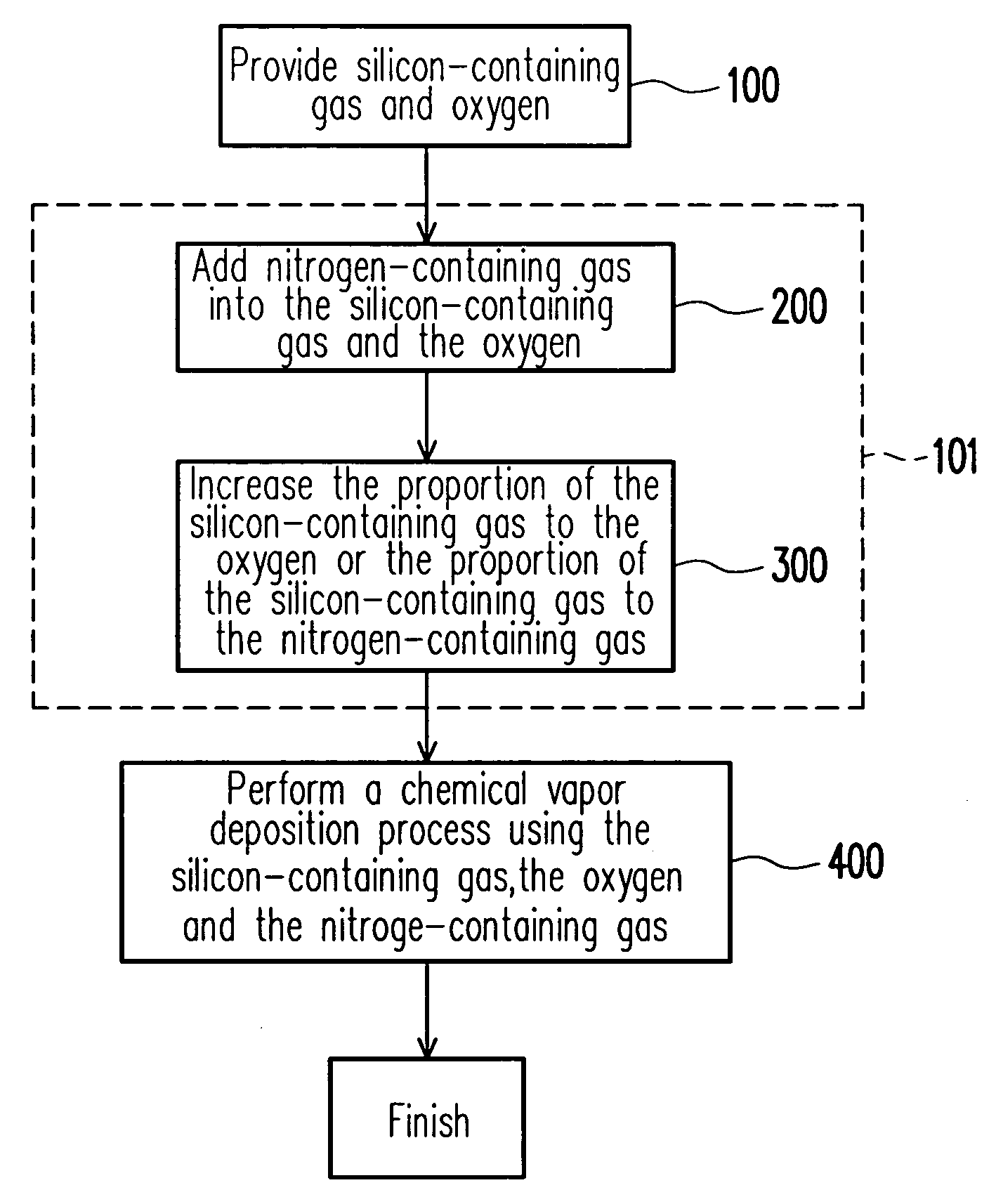
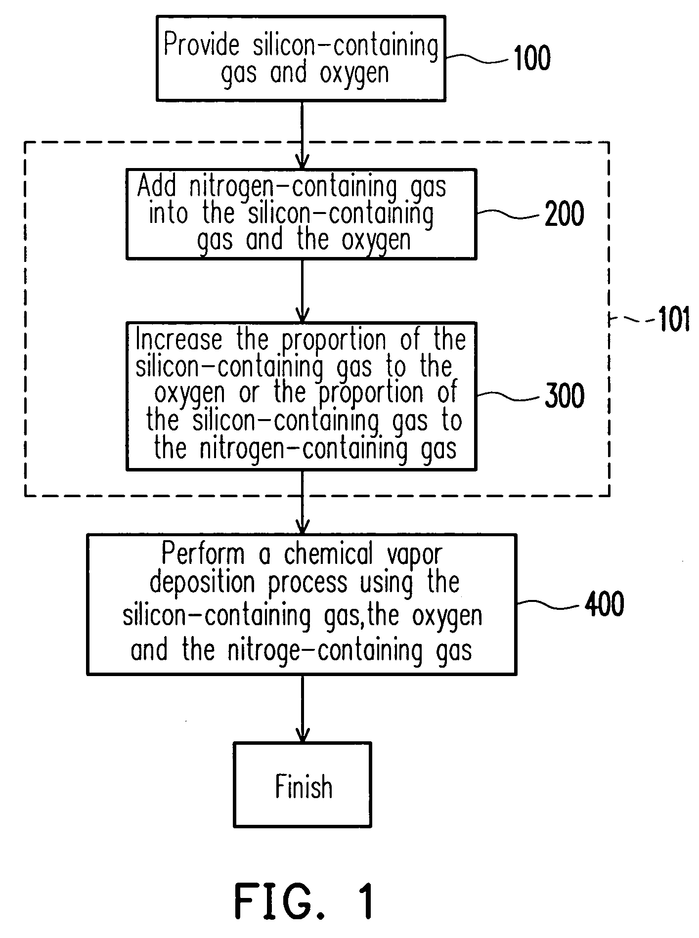
[0019]FIG. 1...


PUM


Abstract

A method for controlling the properties of a dielectric anti-reflective coating (DARC) is provided. In the process of forming the DARC, a nitrogen-containing gas is added to a reaction gas comprising silicon-containing gas and oxygen for controlling the n value of the DARC. Furthermore, the proportion of the silicon-containing gas to the oxygen or the proportion of the silicon-containing gas to the nitrogen-containing gas is increased to control the k value of the DARC. By means of proper control of the n value and the k value, the DARC can have the lowest substrate reflectivity.

Description

BACKGROUND OF THE INVENTION [0001] 1. Field of the Invention [0002] The present invention relates to a method for manufacturing an anti-reflective coating. More particularly, the present invention relates to a method for controlling the properties of a dielectric anti-reflective coating (DARC) and manufacturing DARC. [0003] 2. Description of the Related Art [0004] With the ever-decreasing size of feature line widths in semiconductor manufacturing, photolithographic process is carried out with increasing difficulties. As the line width is decreased, misalignment occurs with increasing frequency especially in the process of defining a conductive layer. Because the reflectivity index of the conductive layer is normally higher than the surrounding dielectric layer or insulation layer, light can easily reflect from the surface of the conductive layer during the definition of a photoresist pattern and lead to a change in dimension. Ultimately, the transferred pattern after the photolithog...

Claims


Application Information

Patent Timeline
IPC IPC(8): H01L21/31
CPCG03F7/091H01L21/0276
Inventor LUO, SHING-ANNLU, CHIEN-HUNGSU, CHIN-TA
Owner MACRONIX INT CO LTD
Why Eureka
Try Eureka