Port design and method of assembly

a technology of access ports and ports, which is applied in the direction of medical devices, other medical devices, etc., can solve the problems of difficult to provide welding between the septa and the septa in the access port, and difficult to obtain closely matched mating features with complex profiles with injection molding, so as to improve the ability to weld ultrasonic features and reduce the potential strain or creep of plastic features that compress the septa during and after assembly

Inactive Publication Date: 2006-06-01
CR BARD INC
View PDF26 Cites 103 Cited by
  • Summary
  • Abstract
  • Description
  • Claims
  • Application Information

AI Technical Summary

Benefits of technology

[0008] Accordingly, described herein are access ports which incorporate improved ultrasonic weld features. In one variation, the access port includes a dual port design with a built-in weld feature, which includes an energy director positioned on the top surface of the port base and a corresponding flat on the underside of the port top. Silicone rubber septa are captured between the port top and the port base during the ultrasonic welding process. Cylindrical features on the port top and the port base may provide general alignment during the assembly process. In this particular design, since the energy director on the base needs only to contact the flat surface on the top, precision alignment between the port top and port base is not required. Far field welding may then be utilized to weld the joint between the port top and the port base. Furthermore, since the weld occurs at the top of the port base adjacent the captured silicone septa, the potential strain or creep of the plastic features that compress the septa during and after assembly may be reduced by minimizing the amount of material between the weld joint and the load created by the compressed silicone rubber septa.

Problems solved by technology

It is difficult to obtain closely matched mating features having a complex profile with injection molding.
In addition, with the shear joint design it is difficult to provide welding between the septa in the access ports while maintaining a narrow profile between the septa.

Method used


Image

  • Port design and method of assembly
  • Port design and method of assembly
  • Port design and method of assembly

Examples


Embodiment Construction

, in conjunction with the accompanying drawings that are first briefly described.

BRIEF DESCRIPTION OF THE DRAWINGS

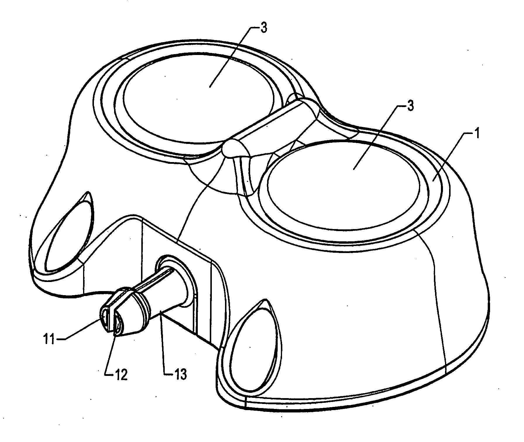
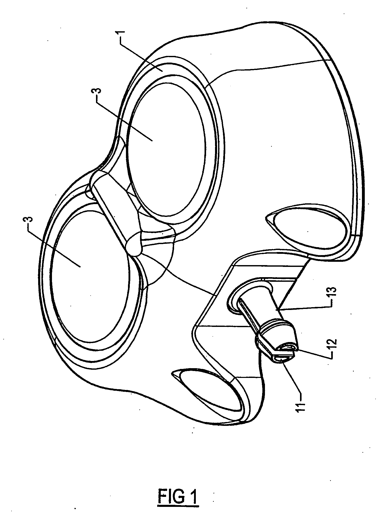
[0010]FIG. 1 illustrates one variation of a dual chamber access port.

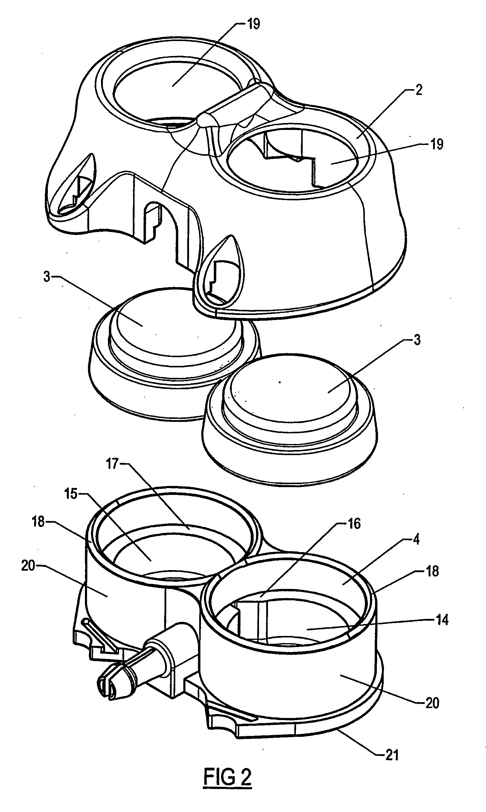
[0011]FIG. 2 illustrates the dual chamber access port of FIG. 1 in a pre-assembled condition. As shown, the dual chamber access port includes a port top, two septa and a port base.

[0012]FIG. 3A illustrates a semi-assembled dual chamber access port prior to bounding of the port top to the port base through ultrasound welding.

[0013]FIG. 3B is an inset figure from FIG. 3A, showing an expanded view of the joint between the port top and the port base. An energy director is shown protruding from the port base and the port top sits on the tip of the energy director.

[0014]FIG. 4A illustrates the access port assembly of FIG. 3A after the parts are assembled through ultrasound welding of the port top to the port base. In the welding process the septa are secured between the port top and the port base.

[0015]...


PUM


Abstract

An access port assembly having an ultrasonic weld energy director and method of assembling the access port utilizing the energy director. The access port may include a dual chamber port base and a port top for securing two septa on the base. An energy director may be positioned on the top end of the port base and a corresponding flat may be provided on the underside of the port top for receiving the energy director. Once the port top is aligned on top of the port based with the septa positioned in-between, far field welding may be implemented to connect the port top to the port base. The access port assembly may be further configured such that when the components are assembled for welding, the weld area is confined from air surrounding the port assembly.

Description

PRIORITY [0001] This application claims the benefit under 35 U.S.C. § 119(e) of U.S. Provisional Application No. 60 / 591,387, filed Jul. 26, 2004, which is expressly incorporated by reference as if fully set forth herein.BACKGROUND [0002] The present invention generally relates to a subcutaneously implantable access port. More specifically, the present invention relates to access port design and method for assembling an access port. [0003] A variety of subcutaneously implantable access ports have been utilized by physicians to deliver fluids to, or withdraw fluids from, the bloodstream or other subcutaneous cavities inside a patient. One example of such an access port includes a needle-impenetrable housing, which encloses one or more fluid cavities and defines, for each of such fluid cavities, an access aperture communicating through the housing on the side thereof, which is adjacent to the skin of the patient where the access port is implanted into the body of a patient. A needle-pe...

Claims


Application Information

Patent Timeline
Patent Type & Authority Applications(United States)
IPC IPC(8): A61M31/00
CPCA61M39/0208A61M2039/0214
Inventor HAMATAKE, BRET
Owner CR BARD INC
Why Eureka
Try Eureka