Vascular graft

a vascular graft and graft technology, applied in the field of vascular grafts, can solve the problems of initiation of disease formation, moderate long-term patency rate of conventional vascular bypass procedures, etc., and achieve the effect of enhancing the impingement of the first branch and minimising the possibility of disease formation

Inactive Publication Date: 2006-06-01
UNIVERSITY OF LIMERICK
View PDF17 Cites 2 Cited by
  • Summary
  • Abstract
  • Description
  • Claims
  • Application Information

AI Technical Summary

Benefits of technology

[0010] In one embodiment of the invention the graft is configured to discharge flow out of the first branch to impinge upon flow being discharged out of the second branch. By discharging the flow out of the first branch to impinge upon the flow being discharged out of the second branch, this results in the flow impingement occurring at a central region of the lumen away from the interior walls. In particular the flow exiting from the first branch impinges upon the flow exiting from the second branch, and as a result prevents the second branch flow from impinging on the interior wall. In a similar manner, the second branch flow impinges upon the first branch flow, and as a result prevents the first branch flow from impinging on the interior wall. By preventing the flow from impinging on the interior wall

Problems solved by technology

However, conventional vascular bypass procedures have moderate long term patency rates, typically between 33% and 41% at 60 months.
Conventional vascular gr

Method used


Image

  • Vascular graft
  • Vascular graft
  • Vascular graft

Examples


Embodiment Construction

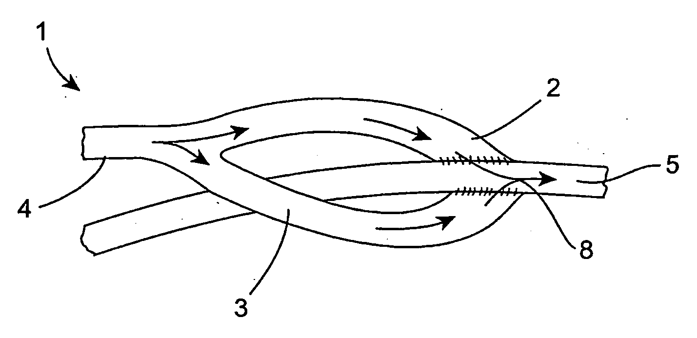
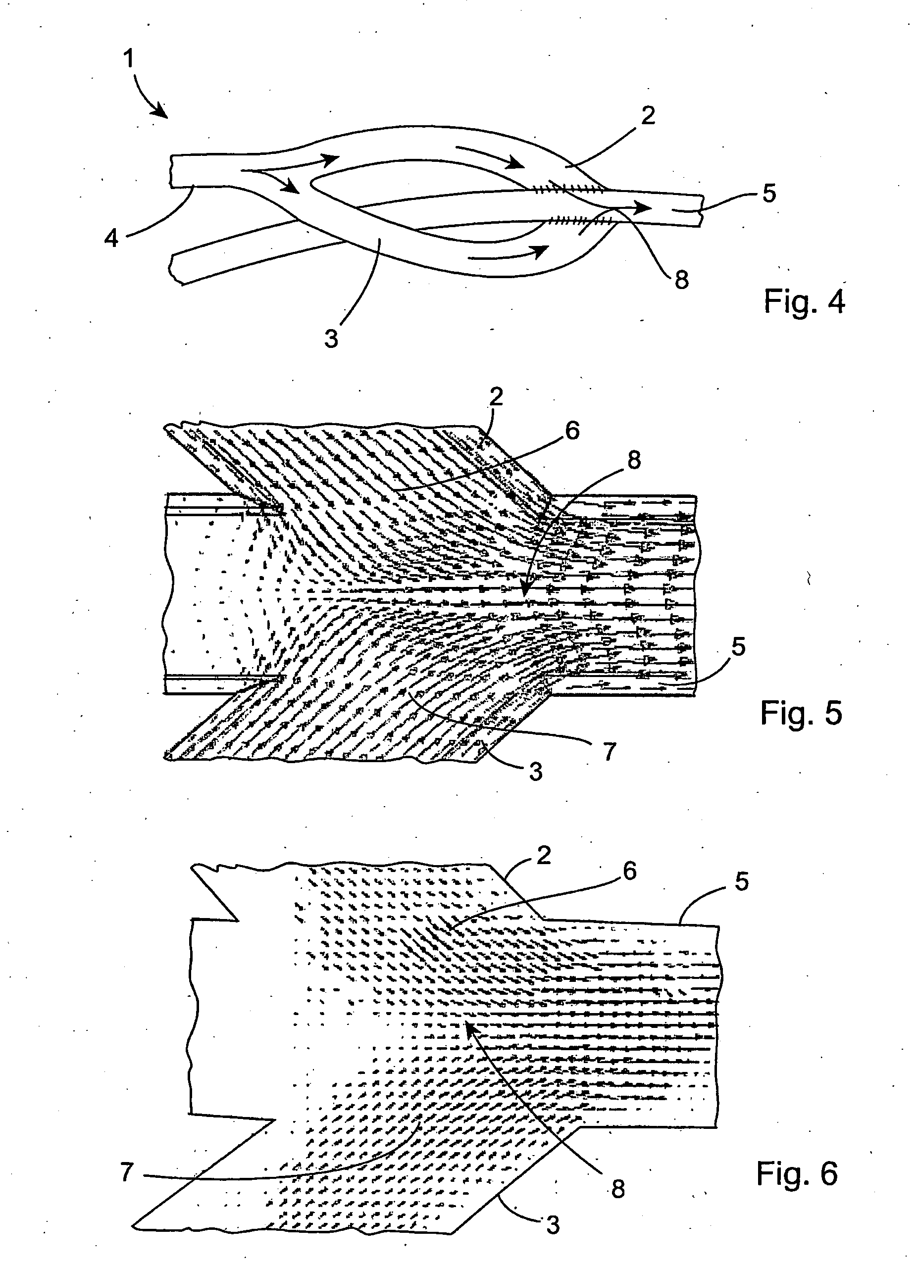
[0042] Referring to the drawings, and initially to FIGS. 4 to 10 thereof, there is illustrated a vascular graft 1 according to the invention for directing blood flow between a first vasculature part and a second vasculature part 5.

[0043] The first vasculature part and the second vasculature part 5 may be parts of the same vascular vessel. In such a case, the graft 1 directs blood flow from an upstream part of a vascular vessel to a downstream part of the same vascular vessel.

[0044] Alternatively the first vasculature part and the second vasculature part 5 may be parts of different vascular vessels. In such a case, the graft 1 directs blood flow from an upstream part of one vascular vessel to a downstream part of a different vascular vessel.

[0045] The graft 1 comprises a proximal flow conduit 4 for directing blood flow from the first vasculature part to a first branch 2 and to a second branch 3. The first branch 2 directs the blood flow from the proximal flow conduit 4 to the seco...


PUM


Abstract

A vascular graft (20) comprises a proximal section (4), integral with two branches (2, 3) which terminate in a distal end-to-end section (30). The end-to-end section (30) is attached to a host artery (5) at end-to-end anastomoses (31, 32). Flow of blood from the proximal section (4) to the host artery (5) occurs with a self-correcting flow pattern at the opposing junctions, avoiding arterial bed impingement and associated risk of restenosis.

Description

INTRODUCTION [0001] This invention relates to a vascular graft and to a method of performing a vascular bypass procedure. [0002] It is known to achieve the restoration of blood supply to ischemic limb extremities by using a vascular bypass graft, and this enables normal limb function to be maintained. A typical conventional vascular graft is illustrated in FIG. 1. [0003] However, conventional vascular bypass procedures have moderate long term patency rates, typically between 33% and 41% at 60 months. Restenosis frequently occurs at the distal anastomosis, forming often on the artery bed opposite to the anastomosis. One major cause of restenosis is the initiation of intimal hyperplasia at this location. Disease formation on the artery bed opposite to the junction is believed to occur due to the abnormal flow patterns created as the flow exits the graft and enters the artery, impinging on the bed of the junction. The flow patterns created by the end-to-side distal anastomosis has been...

Claims


Application Information

Patent Timeline
IPC IPC(8): A61F2/06
CPCA61F2/06A61F2/07A61F2002/065A61F2002/068A61F2/89A61F2220/0075
Inventor WALSH, MICHAEL THOMASMCGLOUGHLIN, TIMOTHY M.GRACE, PIERCE
Owner UNIVERSITY OF LIMERICK
Why Eureka
Try Eureka