
Power management

a power management and power technology, applied in power management, high-level techniques, instruments, etc., can solve problems such as troublesome control shutdown, system power up, circuit still having a slightly different threshold, etc., and achieve the effect of easy system extension

Inactive Publication Date: 2006-06-01
NOKIA SOLUTIONS & NETWORKS OY
View PDF8 Cites 32 Cited by
  • Summary
  • Abstract
  • Description
  • Claims
  • Application Information

AI Technical Summary

Benefits of technology

[0020] It is an advantage of the invention that a direct control is faster and does not rely on other components. It is further an advantage of the invention that it is easy to extend the system by adding another power management circuit. Further, it does not require additional connection pins on the circuits.
[0021] It is equally an advantage of the invention that with a direct control by all power management circuits, the conditions which are checked in the plurality of power management circuits do not have to be adjusted to each other in order to ensure a proper order in which they are detected in the power management circuits. Thus, two or more power management circuits can be employed which are basically the same.
[0022] While the indicated advantages of the invention are achieved when a plurality of power management circuits are employed in an electronic device, it is to be understood that the proposed power management circuit can be used nevertheless as the only power management circuit of an electronic device.
[0023] In one embodiment of the invention, the plurality of power management circuits comprise one master power management circuit and at least one slave power management circuit, where the master power management circuit is able to control any slave power management circuit for powering the electronic device up and down in a regular manner in regular situations. The master power management circuit may be for example the only power management circuit that is being controlled by software to handle a regular power down procedure. The proposed supervision of conditions is only employed for special situations, which may be taken into account as well in the regular situations, though. Such regular situations may be for example a powering up when a user presses an ON / OFF key or in case of a charger connection, or a shut-down of the system due to a request by system software. A master power management circuit may also control a power up reset signal. In another embodiment of the invention, however, the plurality of power management circuits may comprise as well a plurality of power management circuits of the same status. It is to be understood that an electronic device may further comprise at least one power management circuit which is not capable of monitoring an entry of a condition itself, and which is thus not required to be able to change the state of the signal line. Such a power management circuit will simply follow the commands on the signal line.
[0024] In one embodiment of the invention, a condition which allows a change of a powering state of the at least one functional component associated to a power management circuit comprises a condition which allows powering up the at least one functional component. The power management circuits are adapted to change a state of the signal line to cause the at least two power management circuits to power up their associated functional components, in case each of the at least two power management circuits detects a condition which allows powering up associated functional components. That is, the state of the signal line will only indicate that all functional components are to be powered up, in case all power management circuits agree that a condition is met. As long as one or more of the power management circuits considers the condition not to be met, the state of the signal line cannot indicate a powering up of the functional components.
[0025] In a further embodiment of the invention, a condition which requires a change of a powering state of the at least one functional component associated to a power management circuit comprises a condition which requires powering down the at least one functional component. Each of the power management circuits are adapted to change a state of the signal line to cause the power management circuits to power down their associated functional components, in case at least one of the at least two power management circuits detects a condition which requires a powering down of the at least one associated functional component. That is, the state of the signal line will indicate that all functional components are to be powered down, as soon as this is considered necessary by a single one of the power management circuits.

Problems solved by technology

Normally, inserting a battery with a sufficiently high voltage into a device like a mobile phone causes the system to power up, even though this might not be visible to a user.
But even if the cut-off thresholds are selected to be the same in all power management circuits, each power management circuit will still have a slightly different threshold due to an inherent inaccuracy.
As a consequence, a controlled shut down is a problem.
A corresponding problem arises when the system is starting up due to a battery voltage rising above the power-up threshold.
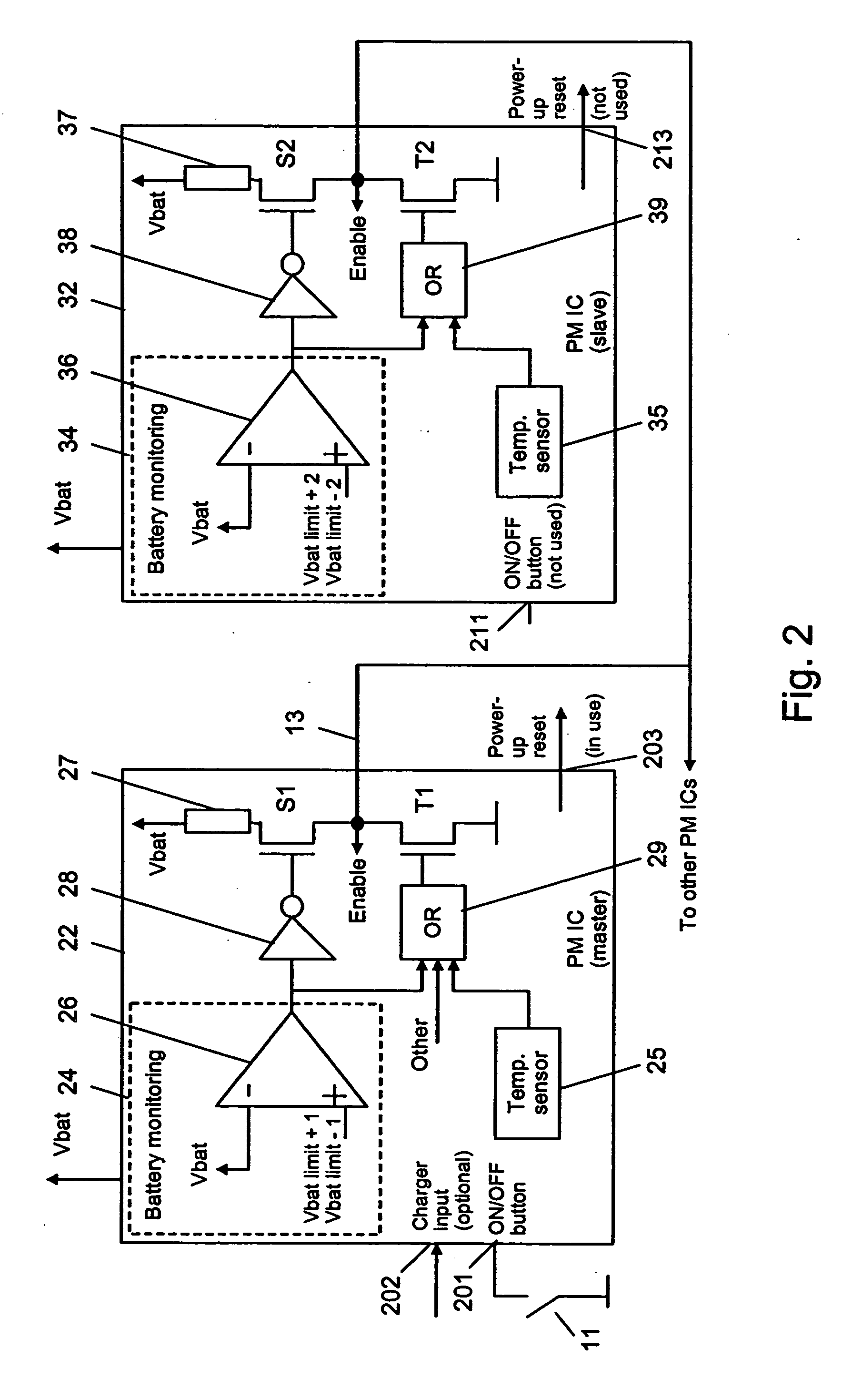
It is a disadvantage of such a system, though, that power management circuits having virtually the same battery voltage thresholds cannot be used as a master power management circuit and as a slave power management circuit within a single electronic device.
Further, the cut-off threshold of the master power management circuit has to be unnecessarily high, in order to guarantee an appropriate voltage regulation in the slave devices.
Further, it is not possible to use any power management circuit as the master power management circuit.
Moreover, it is not possible, to use a slave power management circuit alone or as a master power management circuit, as the cut-off threshold might be too low for a voltage regulation.

Method used


Image

  • Power management
  • Power management
  • Power management

Examples


Embodiment Construction

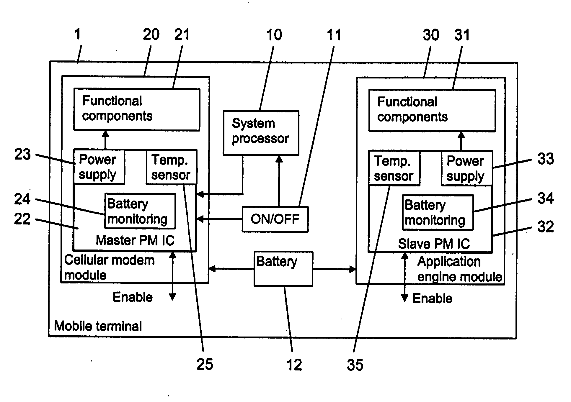
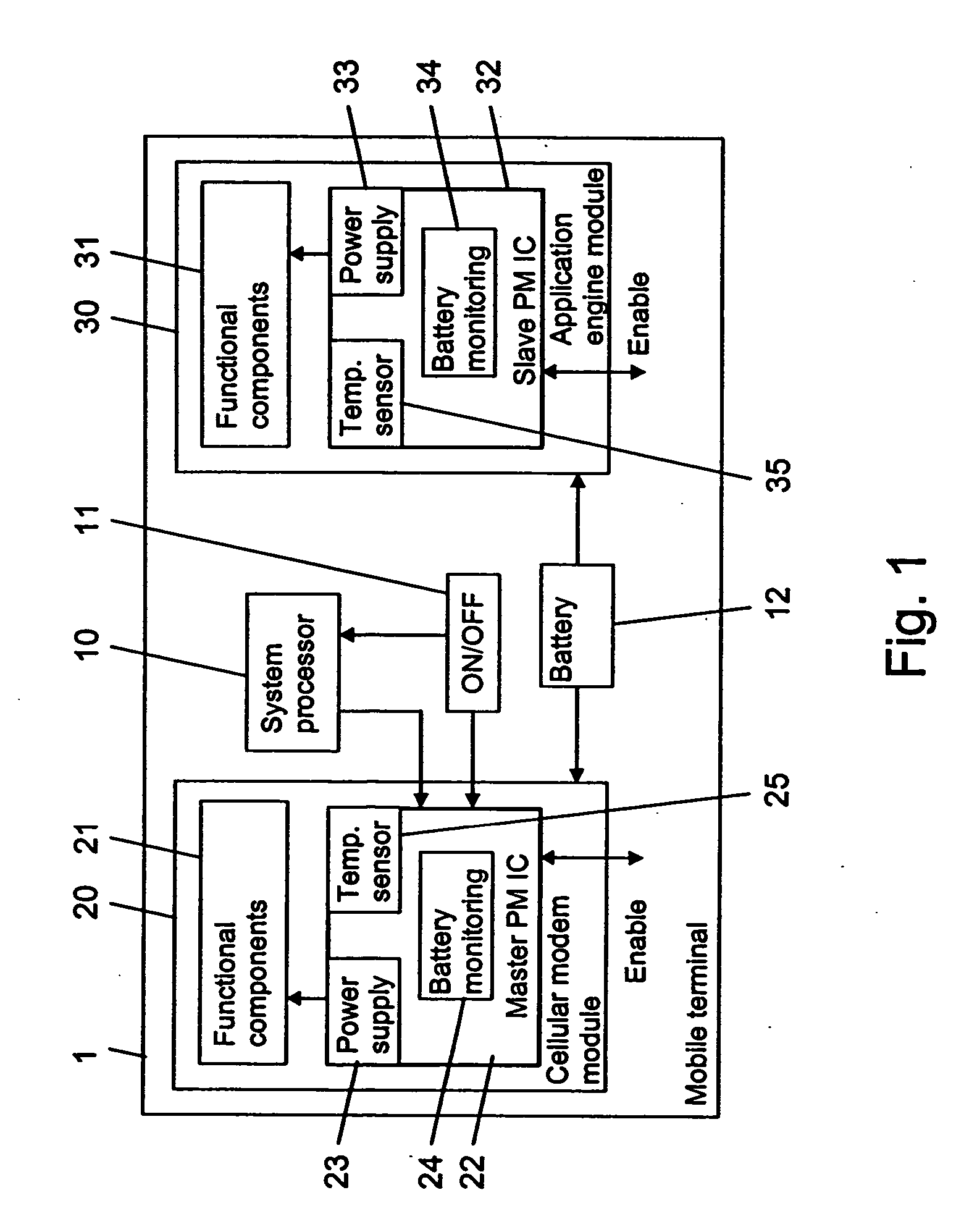
[0042]FIG. 1 is a schematic block diagram of a mobile terminal 1, which enables a flexible implementation of power management circuits in accordance with an embodiment of the invention. It is to be understood that the invention can equally be implemented in any other electronic device comprising a plurality of power management circuits.

[0043] The mobile terminal 1 includes at least one system processor 10, which runs software for coordinating the operations in the mobile terminal 1. The mobile terminal 1 further comprises an ON / OFF button 11 and a battery 12 providing the power supply for the mobile terminal 1.

[0044] The mobile terminal 1 further includes a cellular modem module 20. The cellular modem module 20 comprises functional components 21 for a cellular modem integrated on a chip, including for example a processor, an RF module and memory components. In addition, the cellular modem module 20 comprises a master power management (PM) IC 22. The master PM IC 22 comprises a pow...


PUM


Abstract

Each of at least two power management (PM) circuits interconnected by a signal line is adapted to control a power supply to at least one functional component associated to the power management circuit. Each PM circuit is adapted to detect a condition which allows or requires a change of a powering state of the at least one associated functional component and to contribute to a change of a state of the signal line, in case the PM circuit detects a condition which allows or requires, respectively, a change of a powering state of the at least one associated functional component. Each PM circuit is adapted to monitor a state of the signal line. Each PM circuit is adapted to change a powering state of all associated functional components upon detection of a change of state of the signal line.

Description

FIELD OF THE INVENTION [0001] The invention relates to an electronic device comprising at least two power management circuits. The invention relates equally to a corresponding power management circuit, to a chip comprising such a power management circuit and to a method of operating such an electronic device. BACKGROUND OF THE INVENTION [0002] A power management circuit is a circuit which controls the power supply to at least one functional component of an electronic device. If a device comprises a plurality of functional components, a dedicated power management circuit may be associated to each of these functional components. [0003] For example, a cellular terminal usually comprises a cellular modem as a first functional component, an application engine as a second functional component, etc. The term application engine refers to the “motor” of a terminal. It may comprise the application processor and related memory components, including the core software, hardware drivers, low leve...

Claims


Application Information

Patent Timeline
IPC IPC(8): G06F1/26
CPCG06F1/305G06F1/3203H04W52/0235Y02B60/50Y02D30/70
Inventor NOKKONEN, ERKKI
Owner NOKIA SOLUTIONS & NETWORKS OY
Learn More