Solar power station

Inactive Publication Date: 2006-06-08
HON WAI MAN
View PDF4 Cites 16 Cited by
  • Summary
  • Abstract
  • Description
  • Claims
  • Application Information

AI Technical Summary

Benefits of technology

[0010] If a seismic event has been sensed, the verify parameter subroutine locates the point of highest wave intensity and the epicenter, determines the distance from the solar power station to the point of highest wave intensity and the epicenter, queries the system computer and appropriate personnel to evaluate the intensity of the seismic force to determine the effect on the solar power station and prompts appropriate personnel to make a manual entry to initiate withdrawal of the towers if the evaluation of the seismic event indicates that the seismic force is likely to damage the solar power station. If a high wind force has been sensed, the verify parameter subroutine locates the source of the wind, determines the direction and intensity of the wind force, prompts appropriate personnel to contact a weather bureau to confirm the direction and intensity of the wind force, queries the system computer and appropriate

Problems solved by technology

Error in the gear reducers or linkage between the motor and collector, such as backlash and non-linearly, detracted from the accuracy.
When high accuracy was required, the gear reducers were very expensive.
These conventional solar power systems occasionally suffered damage from high winds.
The electric elevation actuators and high ratio speed reducers utilized by these systems were very slow to put the collector into wind stow, sometimes taking as long as forty-five minutes.

Method used


Image

  • Solar power station
  • Solar power station
  • Solar power station

Examples


Embodiment Construction

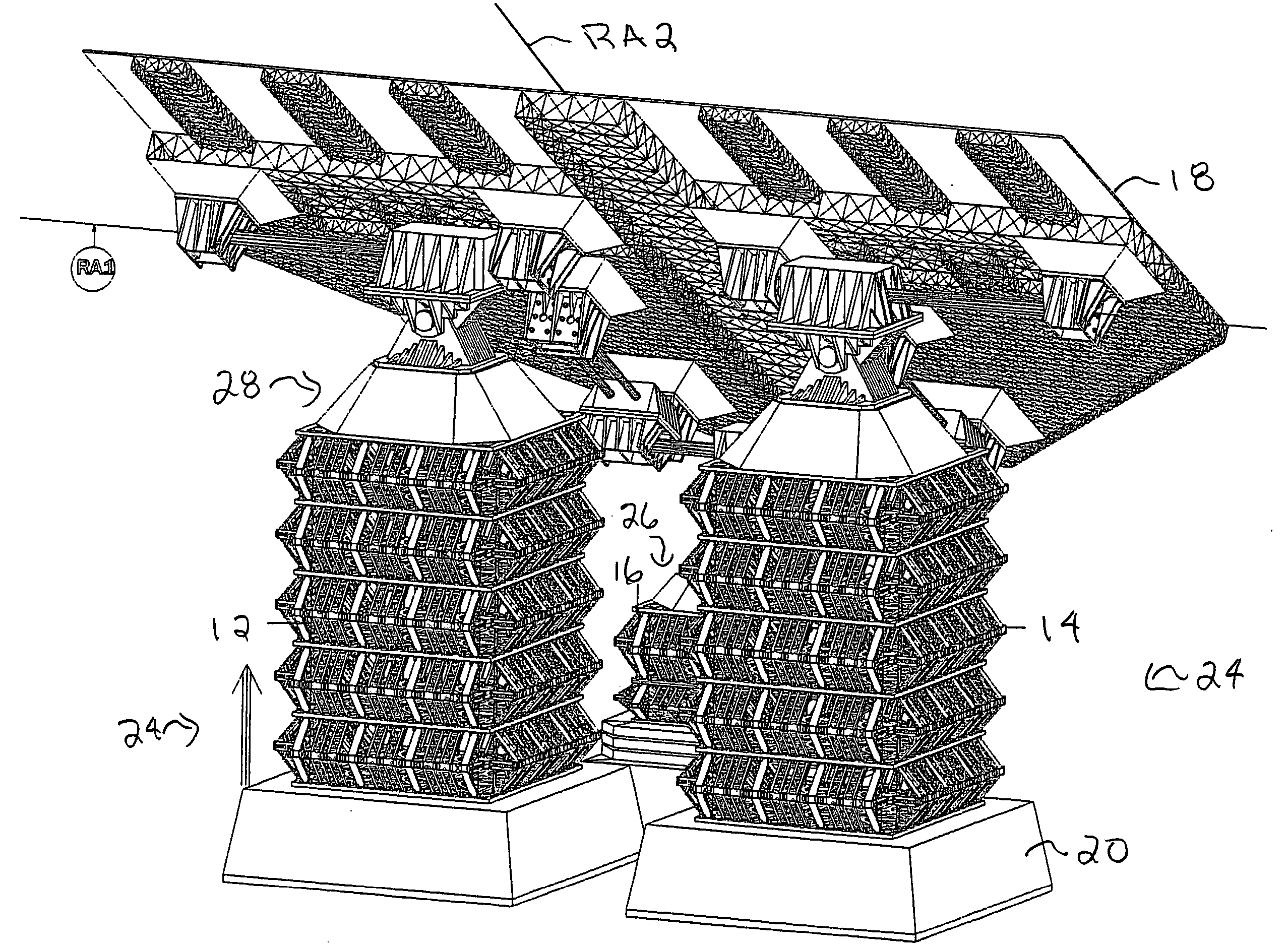
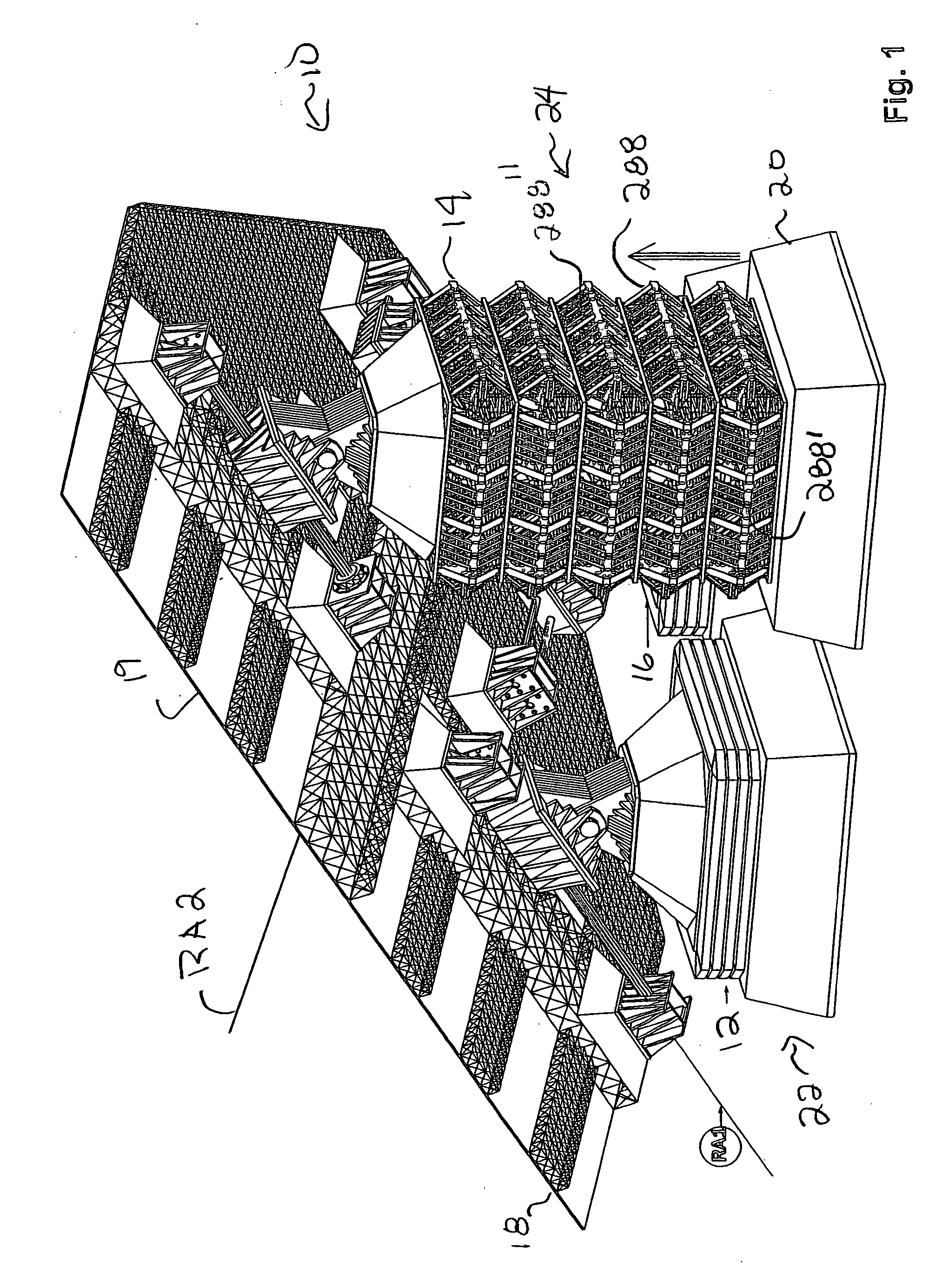
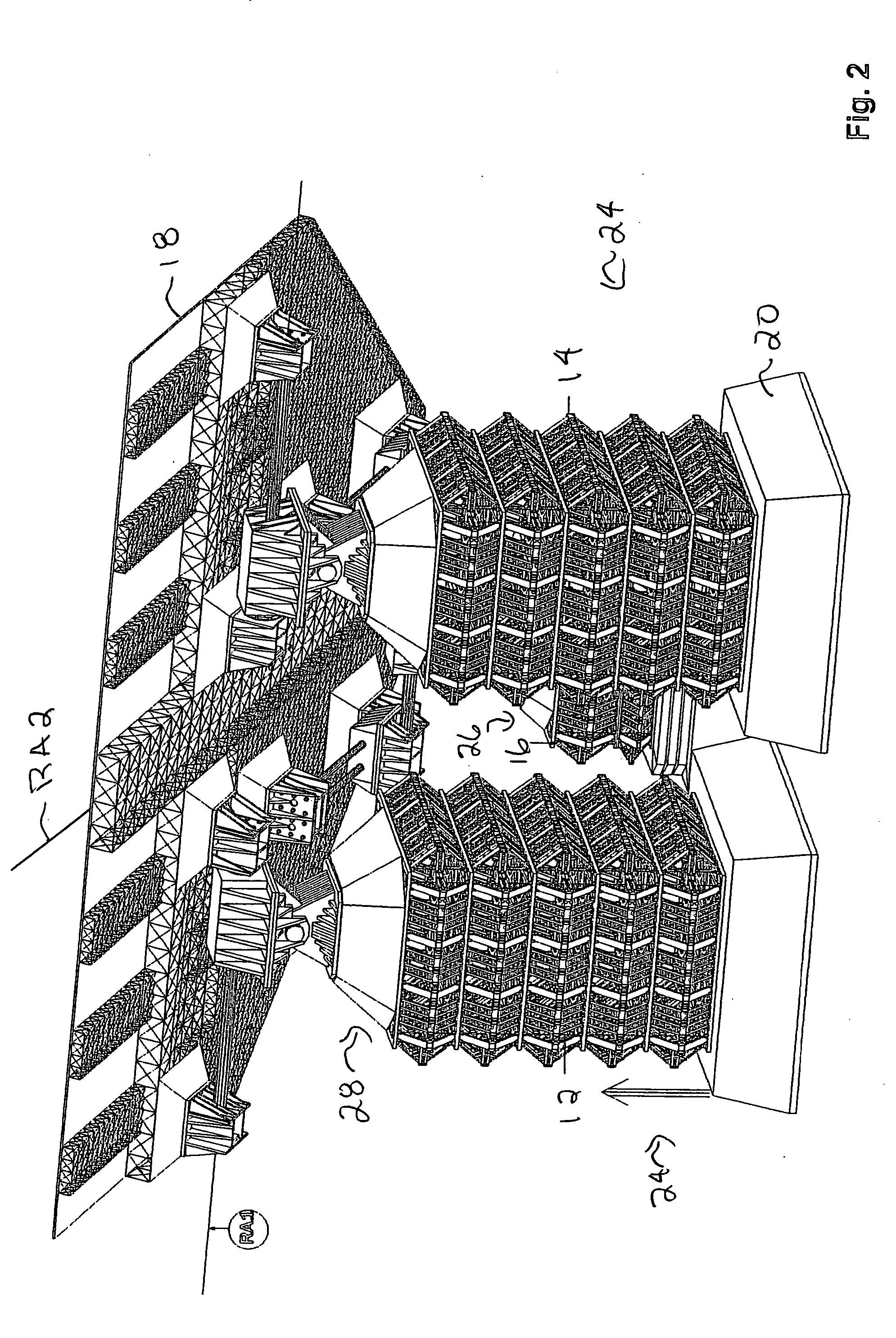
[0077] With reference to the drawings wherein like numerals represent like parts throughout the several figures, a solar power station in accordance with the present invention is generally designated by the numeral 10. The solar power station 10 includes three, substantially identical, dynamic steel truss towers 12, 14, 16 supporting a solar panel assembly 18. Supports 20 at the ground floor stabilize and support each of the towers 12, 14, 16. It should be appreciated that the solar panel assembly 18 is positioned to optimize collection of sunlight and that the operating description provided below is for illustration purposes only. The operation of the towers 12, 14, 16 for orienting the solar panel assembly 18 depends on the topography, latitude and longitude of the installation site.

[0078] The solar power station 10 shown in FIGS. 1-3 is installed such that the planar solar panel 19 of the solar panel assembly 18 of FIG. 1 is positioned to receive sun light at sunrise, the solar ...


PUM


Abstract

A method of operating a solar power station solar power station including a solar panel assembly having multiple towers, a solar panel pivotally mounted to an upper end of each tower, and a control system. Each of the towers has multiple floors and is individually extendable from a bottom position to an extended position. The control system includes a main routine for operating the towers comprising a normal operation subroutine for selectively positioning the towers between the bottom position and the extended position, whereby the solar power panel is positioned for maximum solar collection. A monitor parameter subroutine continually monitors the earthquake and wind sensors. A withdraw towers subroutine initiates withdrawal of the towers to the bottom position when the earthquake sensor or the wind sensor sense a seismic event or a high wind force, respectively, that is likely to damage the solar power station. A recover from event subroutine returns control from the withdraw towers subroutine to the normal operation subroutine when the seismic event or high wind force is no longer likely to damage the solar power station.

Description

CROSS-REFERENCE TO RELATED APPLICATIONS [0001] This application is a continuation-in-part of copending U.S. patent application Ser. No. 11 / 001,862 filed Dec. 2, 2004.BACKGROUND OF THE INVENTION [0002] This invention relates generally to solar power systems. More particularly, the present invention relates to solar power systems having a tracking system for accurately pointing a solar collector at the sun throughout the day. [0003] Early solar power systems included solar tracking systems employing two independent drives to tilt the solar collector about two axes. The first, an elevation axis, allowed the collector to be tilted within an angular range of about ninety degrees between “looking at the horizon” and “looking straight up”. The second, an azimuth axis, is required to allow the collector to track from east to west. The required range of angular rotation depends on the earth's latitude at which the solar collector is installed. For example, in the tropics the angular rotation...

Claims


Application Information

Patent Timeline
IPC IPC(8): F24J2/46F24S50/20
CPCF24J2/40F24J2/4638F24J2/5424F24J2002/5451F24J2002/5455Y02E10/47F24S30/455F24S40/85F24S50/00F24S2030/131F24S2030/132
Inventor HON, WAI MAN
Owner HON WAI MAN
Why Eureka
Try Eureka