Laser cutting device, laser cutting method, and laser cutting system

a laser cutting and laser cutting technology, applied in the direction of manufacturing tools, welding/soldering/cutting articles, transportation and packaging, etc., can solve the problems of poor production efficiency, high manufacturing cost, and difficulty in introducing blanking lines, and achieve the effect of preventing dust adhesion

Inactive Publication Date: 2006-06-08
TOYOTA STEEL CENT CO LTD
View PDF19 Cites 84 Cited by
  • Summary
  • Abstract
  • Description
  • Claims
  • Application Information

AI Technical Summary

Benefits of technology

[0018] The present invention has been made in view of the above facts, and it is an object thereof to provide a laser cutting device and a method for laser cutting with which it is possible to perform laser cutting of parts of various shapes through easy control, to prevent adhesion of dust or similar and scratches being formed in cut parts, and to send out such parts while reliably supporting the same.
[0019] It is another object of the present invention to provide an extremely compact laser cutting system, which does not require exclusive molds or a variety of coil strips of different sheet width such that it is possible to reduce, to the utmost, the number of stocks, spaces for storing the same and also the number of rewinding the coil strips, and is thus favorable for use in high-mix low-volume production.

Problems solved by technology

However, such blanking lines required exclusive molds for each of the parts so that a large space for storage and maintenance of such exclusive molds and personnel are accordingly required.
While overseas production is increasingly being performed, introduction of blanking lines was difficult owing to the small amount of production thereof.
However, since such a conventional laser cutting device employs a pin holder conveyer as the material supporting means that is provided at a downward portion of the processing head so as to move in an orbiting manner, it is actually impossible to provide a dust-collecting means that collects spatter or dust (spatter after cooling) that is generated when performing laser cutting.
Consequently, dust or similar may adhere to rear surfaces of cut parts wherein scratches may be formed in press-molded articles in following processes due to influences of such adhering dust.
It was accordingly necessary to cleanly wipe each of the rear surface of the cut parts off which resulted in poor production efficiency and higher manufacturing costs.
Accordingly, when laser light is repeatedly irradiated onto the same spot, it might happen that degradations in strength of the supporting members resulted in cutting, and thus necessitated periodical exchanges.
Accordingly, control thereof was extremely troublesome since it was necessary to frequently increase or decrease the amount of movement of the material in the feeding direction by the material transferring means or to frequently perform inversion between forward and reverse.
Particularly in case shapes of products included portions of acute angles, it would happen that movements of the material transferring means could not follow movements of the processing head.
Further, since a pin holder conveyer or a pin holder table comprised of a plurality of supporting members was used in the laser cutting devices of the above Patent Reference 1 and Patent Reference 2, drawbacks were presented, depending on pitch clearances of the pin holders, that cut parts (particularly small-sized parts etc.) could not be sent out upon reliably supporting the same.
Moreover, when absorbing and holding cut parts supported by the pin holder conveyer or the pin holder table through a transportation robot or similar, cut parts would be pressed against the pin holder conveyer or the pin holder table so that it would happen that scratches were formed on rear surfaces of the cut parts.
Accordingly, the laser cutting systems employing the laser cutting devices of Patent Reference 1 and Patent Reference 2 were not established as effective systems, and in practice, blank materials were cut by using conventional blanking presses.

Method used


Image

  • Laser cutting device, laser cutting method, and laser cutting system
  • Laser cutting device, laser cutting method, and laser cutting system
  • Laser cutting device, laser cutting method, and laser cutting system

Examples


Embodiment Construction

[0083] The present invention will now be explained below in details.

Laser Cutting System

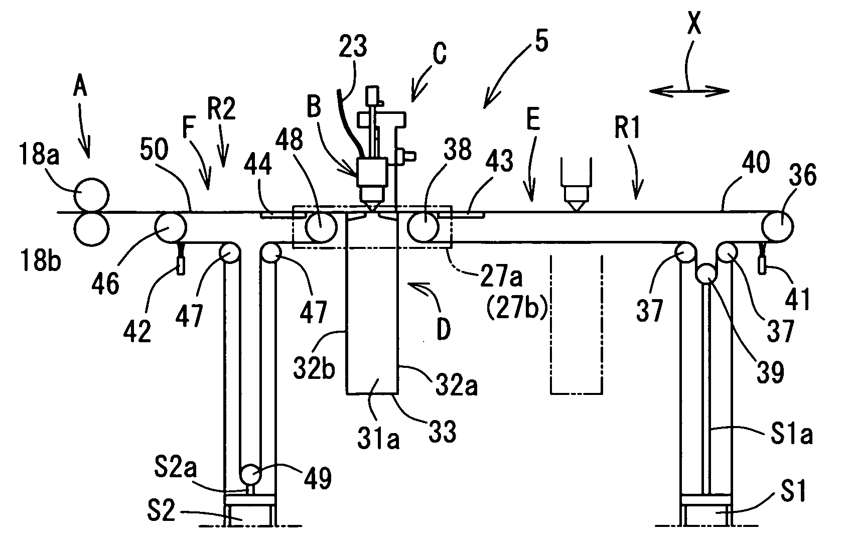
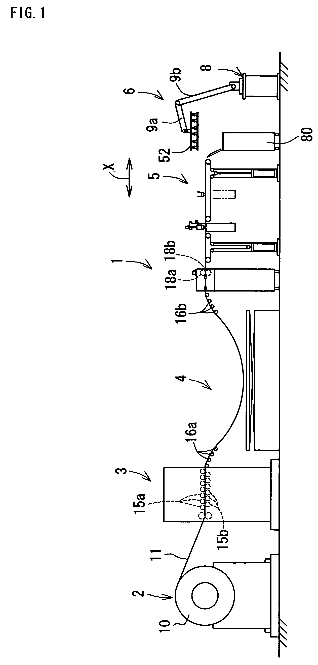
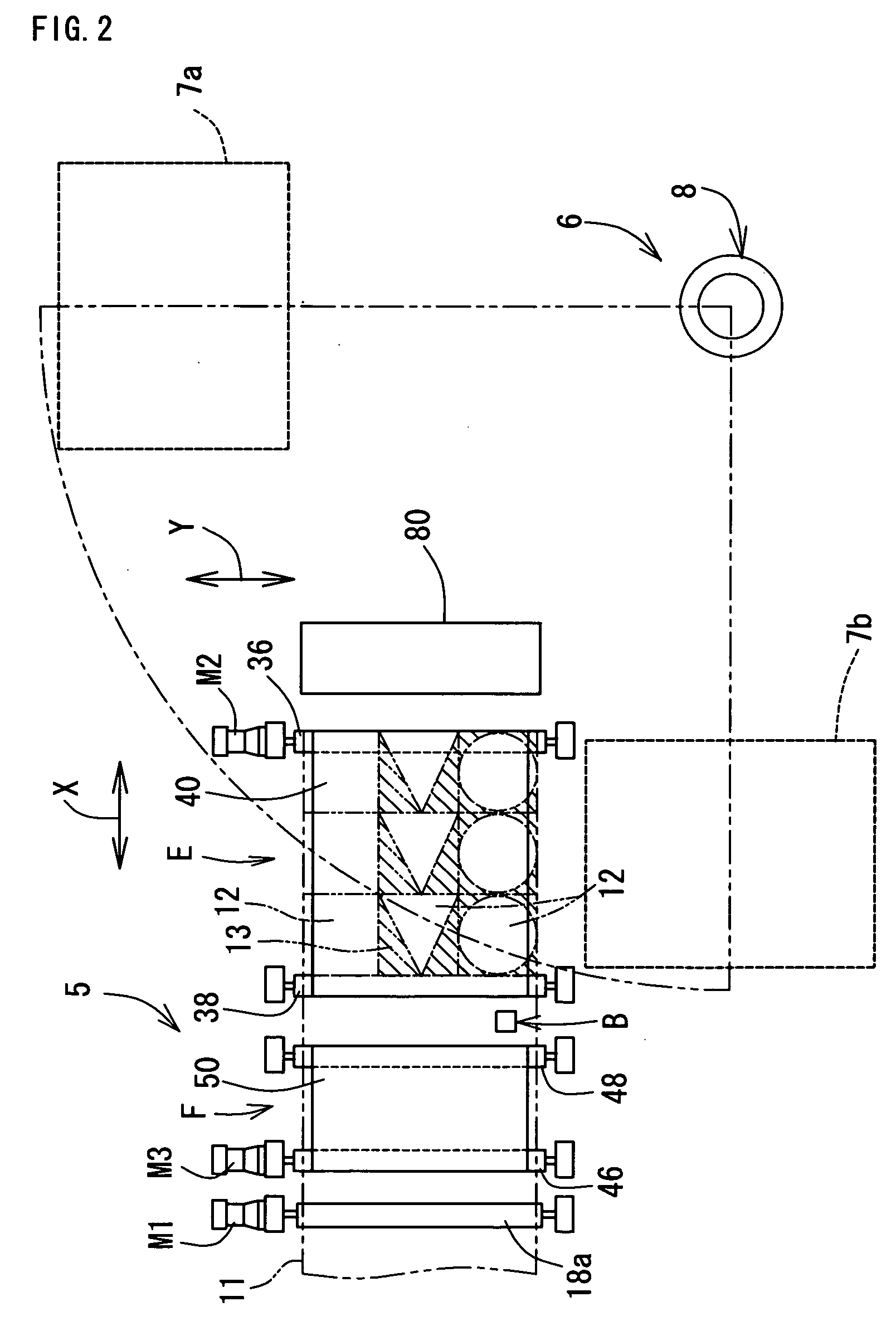
[0084] The laser cutting system according to the present embodiment is comprised to include a coil strip supporting device, a leveler device and a laser cutting device as will be explained hereinafter.

[0085] The laser cutting system may include any one of a loop forming device, a separating and collecting device and a laser welding device as will be explained hereinafter.

[0086] Structures or sizes of the above “coil strip supporting device” are not particularly limited as long as it can support a coil strip such that sheet-like materials can be wound out from the coil strip.

[0087] Structures or sizes of the above “leveler device” are not particularly limited as long as it is provided on a downstream side of the above coil strip supporting device and as long as it is capable of flatly expanding the materials would out from the coil strip.

[0088] Structures or sizes of the above “loop forming ...


PUM

PropertyMeasurementUnit
outer diameteraaaaaaaaaa
widthaaaaaaaaaa
tensionaaaaaaaaaa

Abstract

It is an object of the present invention to provide a laser cutting device, a method for laser cutting and a laser cutting system with which it is possible to perform laser cutting of parts of various shapes through easy control, to prevent adhesion of dust or similar and scratches being formed in cut parts, and to send out such parts while reliably supporting the same. The present laser cutting device 5 is comprised with a material transferring means A that transfers a sheet-like material 11 in a feeding direction, a processing head B that is capable of irradiating laser light towards the material, a head moving means C that makes the processing head move in the feeding direction X and a width direction Y of the material, an upstream-sided supporting means (belt conveyer mechanism F) that supports the material on an upstream side of a downward portion of the processing head and that expands and contracts a supporting region R2 for the material accompanying movements of the processing head in the feeding direction, and a downstream-sided supporting means (belt conveyer mechanism E) that supports cut parts on a downstream side of a downward portion of the processing head and that expands and contracts a supporting region R1 for the cut parts accompanying movements of the processing head in the feeding direction.

Description

BACKGROUND OF THE INVENTION [0001] 1. Field of the Invention [0002] The present invention relates to a laser cutting device, a method for laser cutting and a laser cutting system. More particularly, the present invention relates to a laser cutting device and a method for laser cutting with which it is possible to perform laser cutting of parts of various shapes through easy control, to prevent adhesion of dust or similar and scratches being formed in cut parts, and to send out such parts while reliably supporting the same. The present invention further relates to an extremely compact laser cutting system, which does not require exclusive molds or a variety of coil strips of different sheet width such that it is possible to reduce, to the utmost, the number of stocks, spaces for storing the same and also the number of rewinding the coil strips, and is thus favorable for use in high-mix low-volume production. [0003] The present invention is widely used in the field of, for instance, l...

Claims


Application Information

Patent Timeline
Patent Type & Authority Applications(United States)
IPC IPC(8): B23K26/38B23K26/08B23K26/10B23K26/16B23K26/60B23K26/70B23K101/16B23Q7/03B65G15/12
CPCB23K26/0846B23K26/0876B23K2201/16B23K26/38B23K26/16B23K2101/16
Inventor AOKI, TATSUHIKOHAMAJI, MASANORIHIROSE, YASUHIRO
Owner TOYOTA STEEL CENT CO LTD
Why Eureka
Try Eureka