
Driving device

a technology of driving device and lens barrel, which is applied in the direction of generator/motor, instrument, lens, etc., can solve the problems of reducing the size and cost of the lens barrel, reducing reliability, and being susceptible to so as to stabilize the position, and reduce the effect of gravity

Inactive Publication Date: 2006-06-08
TAIYO YUDEN KK
View PDF2 Cites 25 Cited by
  • Summary
  • Abstract
  • Description
  • Claims
  • Application Information

AI Technical Summary

Benefits of technology

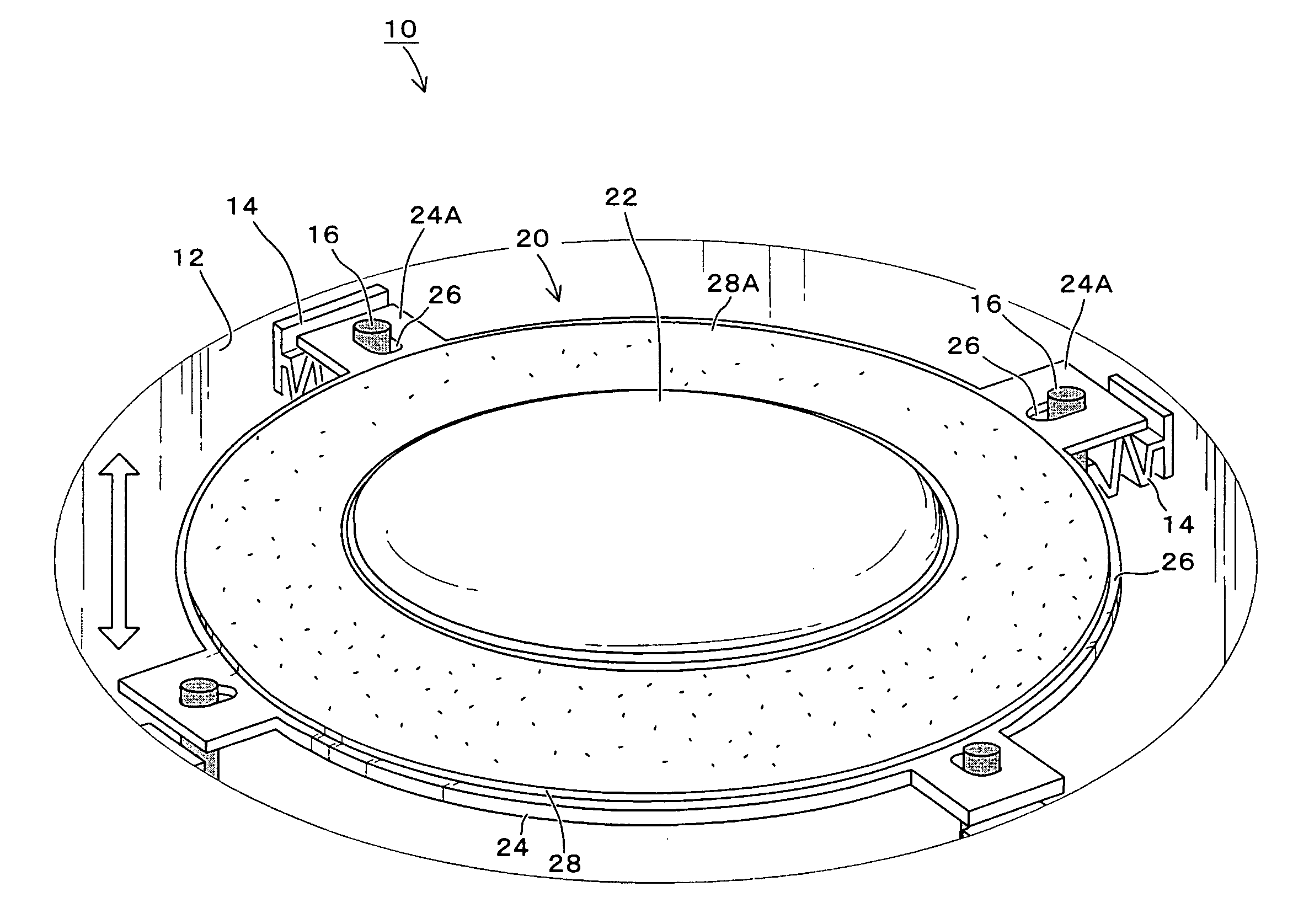
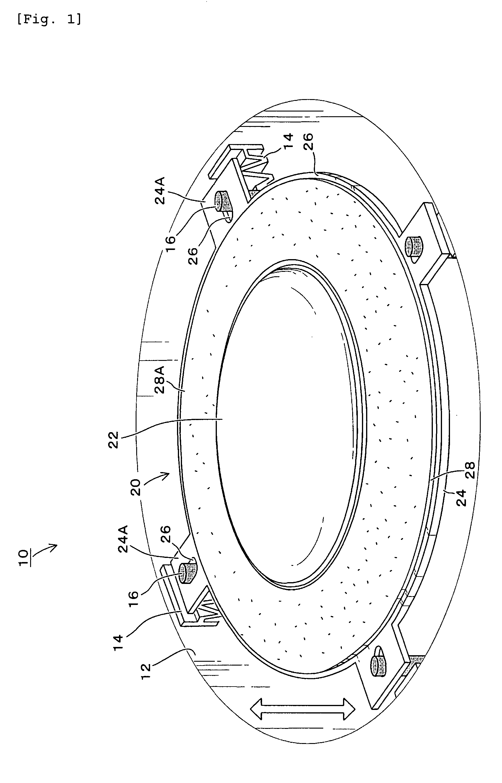
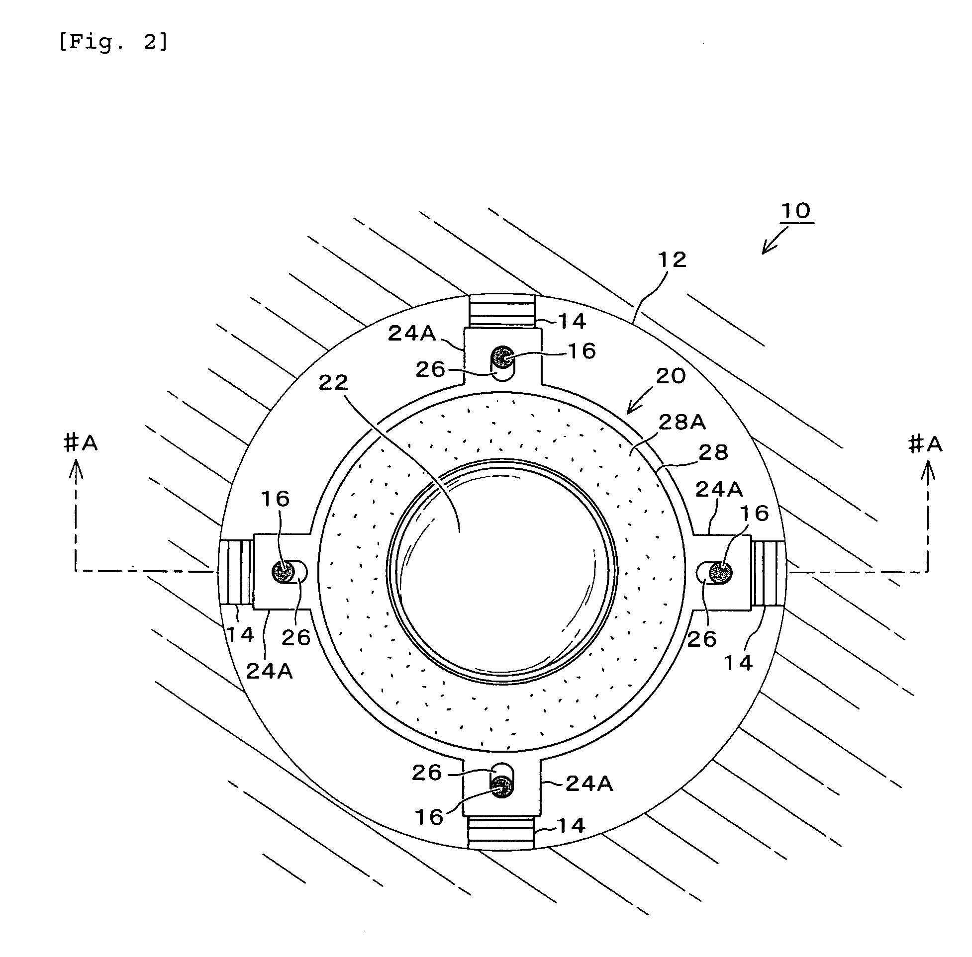
[0012] The present invention addressed the foregoing points and it is an object of the present invention to provide a driving device, which is small in size and light in weight but capable of performing a position control relative to the direction of displacement and also stable displacement and alignment, while reducing the effect of gravity.
[0016] According to the invention, the driving device, for moving a displacement object within a passageway, is integrally provided with a surface-deforming element that is to flex on an applied voltage and a displacement object. By utilizing at least one urging means for giving a tensile force in a direction substantially orthogonal to a moving direction of the displacement object, the surface-deforming element is to be held by applying a tensile force to an outer periphery thereof in a direction from an inner to outer of the passageway. Accordingly, position can be stabilized while reducing the effect of gravity. Despite small in size and light in weight, the driving device is able to carry out stable displacement and alignment.

Problems solved by technology

However, in the background art shown in JP-A-4-69070, problems remain in size and cost reduction because of non-integral structure of the driving rod 117 and the lens barrel 101 to be displaced.
Moreover, because of the driving force orthogonal to fixing force, a fixing force theoretically could not be directly suppressed by a driving force, leaving a problem in respect of reliability.
Furthermore, the lens barrel 101 is susceptible to the effect of gravity because it hangs relative to the driving rod 117.
Still, in the art described in JP-A-8-207755, size reduction is not easy because the frictional force due to the clamp legs 204 is necessary as a holding force for the actuator.
There are also problems of low displacement efficiency and low durability because the clamp legs 204 absorb the vibration of the surface-deforming element 200.
Furthermore, there is a disadvantage of low displacement speed because the resonant frequency of the actuator readily lowers making it impossible to increase the driving frequency.
Thus, a discrepancy may arise between a downward movement speed and an upward movement speed, resulting in a disadvantageous variability in displacement speed.
Particularly, in the art of JP-A-8-207755, if there is a variation among the elastic forces of the clamp legs 204, a rotation may readily occur taking a direction orthogonal to the direction of displacement as an axis, making it difficult to control the position.

Method used


Image

  • Driving device
  • Driving device
  • Driving device

Examples


second embodiment

[0060] Referring to FIGS. 10 to 12, a second embodiment is now described. Note that like or corresponding elements to those of the first embodiment are attached with the same references (true for the following embodiments). FIG. 10 is a plan view of a driving device 50 in the present embodiment as viewed in the optical axis direction. FIG. 11 is a cross-sectional view taken along line #C-#C and viewed in the direction of arrow in FIG. 10. Incidentally, FIG. 11A shows a manner a movable member 60 is in a maximal flexure in the upward, FIG. 11B a manner it is free of flexure and FIG. 11C a manner it is in a maximal flexure in the downward.

[0061] A driving device 50 in the present embodiment is structured that a movable member (actuator body) 60, structured to integrate a lens 22 as a displacement object and a piezoelectric vibrator 61, is held by holding guides 52 at tips of springs 14 provided on an inner surface of and directed toward the center of a passageway 12, as shown in FIGS...

third embodiment

[0067] Referring to FIG. 13, a third embodiment of the invention is described. This embodiment shows another example of holding mechanism and urging means. FIG. 13A is a plan view while FIG. 13B is a cross-sectional view taken along line #D-#D and viewed in the direction of arrow in FIG. 13A. The movable member 20 in a driving device 90 of this embodiment is similar in structure to the first embodiment excepting that protrusiones 24A are provided at three points for the vibration plate 24. As shown in FIG. 13, the holding mechanism in this embodiment includes two first holding guides 92 planted on a support 91 in a cantilever form, and one second holding guide 93 having a base 93A rotatably supported on the support 91. Those holding guides 92, 93 are to penetrate through openings 26 in the protrusiones 24A provided on the movable member 20. In a position of the second holding guide 93 closer to the base 93A, a fulcrum 93B is provided to which one end of a wire 94 is connected for pr...

fourth embodiment

[0070] Referring to FIG. 14, a fourth embodiment of the invention is described. Although the foregoing embodiments were structured with a holding mechanism and urging means separately, the present embodiment has a holding mechanism serving also as urging means. In a driving device 90A of this embodiment, the holding mechanism is structured with a plurality of holding guides 98 planted in a cantilever form on a support 91 such that the upper ends thereof are to be spread at a predetermined angle outwardly of a passageway for the movable member 20. The holding guide 98 is formed of a rod member having an elasticity, e.g. a glass fiber or a piano wire, thus serving also as urging means. Due to an elastic force of the holding guide 98, a tensile force is applied, from an inner to outer of the movement passage of the movable member 20, to the outer periphery of the movable member 20 in a direction nearly orthogonal to a movement of the movable member 20. Hooks or evaginations may also be...


PUM


Abstract

A driving device, small in size and light in weight, is to stabilize the position of a surface-deforming element while reducing the effect of gravity thus enabling stable transfer and positioning. The driving device is structured to hold a movable member integrated with a piezoelectric vibrator and a lens by a shaft provided at a tip of a spring extended from an inner surface to center of a passageway. The shaft extends through an opening formed in a protrusion of the movable member. By a tensile force of the spring, the movable member at its outer periphery is pulled radially and held. When applying a voltage with a waveform changing sharply to the piezoelectric vibrator, the movable member flexes maximally upward or downward to have a reduced diameter and an increasing acceleration thereby making a movement. Then, when a frictional force increases, the protrusion is held at a point where the movable member moves. Because of being held by a tensile force, the effect of gravity decreases and hence the movable member is stabilized in position relative to a direction of transfer.

Description

BACKGROUND OF THE INVENTION [0001] 1. Field of the Invention [0002] The field relates to a driving device (actuator) for driving a displacement object, or driven member, by use of a surface-deforming element such as an electromechanical transducer element. [0003] 2. Description of the Related Art [0004] Conventionally, proposals have been made in JP-A-4-69070 and JP-A-7-298654 on the arts for driving a lens or the like used for various optical apparatuses, precision instruments, and video apparatuses, etc., such as cameras, overhead projectors, binocular glasses, copiers, plotters and X-Y drive tables. Those have already been realized in practical application. FIGS. 16A-16C illustrate the disclosure in JP-A-4-69070 wherein FIG. 16A is a schematic view of a driving device while FIGS. 16B and 16C show a relationship between a voltage and a time. The lens driver shown in FIG. 16A has a lens barrel 101 supporting a lens and a guide bar 103 supporting the lens barrel 101 and guiding it i...

Claims


Application Information

Patent Timeline
Patent Type & Authority Applications(United States)
IPC IPC(8): H02N2/00G02B7/08
CPCG02B3/12G02B3/14H02N2/025H01L41/0973H10N30/2047
Inventor DOSHIDA, YUTAKAKISHI, HIROSHITSUKADA, MASAFUMIISHIDA, KATSUEI
Owner TAIYO YUDEN KK
Learn More